
Optical Concentrator and Associated Photovoltaic Devices

a photovoltaic device and optical concentrator technology, applied in the direction of pv power plants, instruments, lenses, etc., can solve the problems of significant drop in the conversion efficiency of pv devices, reduce the surface,

Inactive Publication Date: 2014-12-25
UNIV OF EXETER
View PDF5 Cites 2 Cited by
  • Summary
  • Abstract
  • Description
  • Claims
  • Application Information

AI Technical Summary

Benefits of technology

The patent text discusses the use of solar concentrators to increase the efficiency of solar PV devices. By using a smaller area of PV material and focusing the sun's energy onto it, the efficiency of the device is increased while using a smaller number of solar cells. This method is also cost-effective and can provide environmental protection for the PV material. The text also mentions the use of a solar PV device that can provide both electrical energy and light transmission, making it suitable for use in insulated glazing units.

Problems solved by technology

It has been estimated that to generate about a gigawatt of power using modern PV systems would require an area of approximately four square miles of silicon and the use of such large amounts of silicon is one of the largest hurdles in the mass uptake of solar PV as a possible replacement for fossil fuels.
Solar PV materials are struggling to increase their conversion efficiency and one potential route being taken to reduce the cost of generating electricity from PV systems is to use less PV material in the device itself, however using a smaller area of PV reduces the surface available to the solar energy and this can lead to a significant drop-off in PV device conversion efficiency and to counter this effect, solar concentrators have been used as a means to focus the sun's energy onto the smaller area of PV material.

Method used


Image

  • Optical Concentrator and Associated Photovoltaic Devices
  • Optical Concentrator and Associated Photovoltaic Devices
  • Optical Concentrator and Associated Photovoltaic Devices

Examples


Embodiment Construction

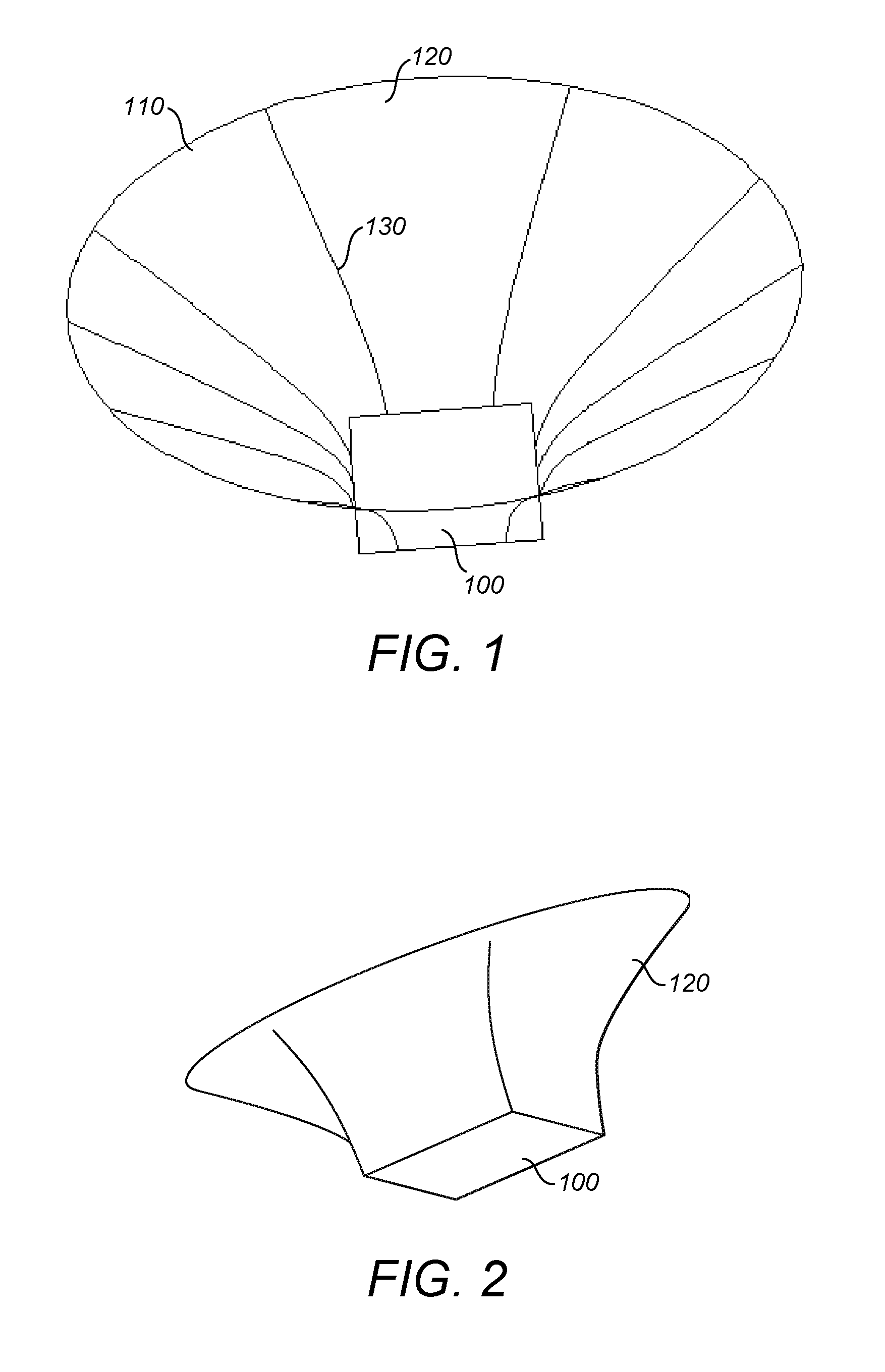
[0033]While the present invention may be embodied in many different forms, a number of illustrative examples are described. Disclosed herein is an optical concentrator for a photovoltaic device that is easily and efficiently produced by well-known plastics or glass production techniques. Also disclosed is a method of making a PV device that incorporates such an optical concentrator.

[0034]Such a device has particular applicability to the fields of building integrated or building applied photo-voltaic energy as the device allows both simultaneous light transmission and photovoltaic energy generation using a reduced area of photovoltaic material.

[0035]Within any PV device described herein the concentrator is arranged to direct and concentrate solar energy to the active surface of a PV material and such a PV device may comprise other materials such adhesive or sealing layers, reflecting or non-reflecting layers, or structures may be present to provide support, adhesion, environmental pr...


PUM

PropertyMeasurementUnit
areaaaaaaaaaaa
Height Aspect Ratioaaaaaaaaaa
rotational angleaaaaaaaaaa

Abstract

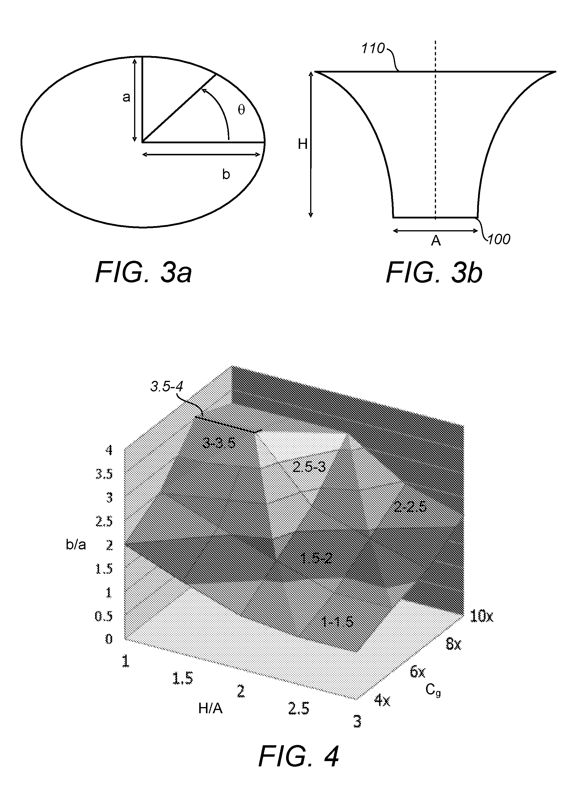
Disclosed is a transmissive optical concentrator comprising an elliptical collector aperture and a non-elliptical exit aperture, the concentrator being operable to concentrate radiation incident on said collector aperture. The body of said concentrator may have a substantially hyperbolic external profile. Also disclosed is a photovoltaic cell employing such a concentrator and a photovoltaic building unit comprising an array of optical transmissive concentrators, each having an elliptical collector aperture; and an array of photovoltaic cells, each aligned with an exit aperture of a concentrator, wherein the area between adjacent collector apertures is transmissive to visible radiation.

Description

[0001]The present invention relates to photovoltaic devices and more particularly to those having an optical component that is capable of concentrating solar energy in an efficient manner and a method of making photovoltaic devices using such components.[0002]As an alternative to fossil fuels, the sun is considered the most abundant natural resource and Solar energy conversion has become commonplace as mass manufacture and increasing efficiency of photovoltaic (PV) materials that convert light to electricity has driven the cost down of PV materials to a level that solar panel arrays are now used to provide power in “off grid” applications, back-up power for portable devices or are being installed or retrofitted to buildings to augment existing power—such installations are known as Building Integrated Photovoltaic (BIPV) or Building Applied Photovoltaics (BAPV).[0003]Solar Energy is actually quite diffuse and due to the seasonal rotation of the Earth on its axis can also vary signifi...

Claims


Application Information

Patent Timeline
Patent Type & Authority Applications(United States)
IPC IPC(8): H01L31/052B29C39/26G02B3/00
CPCH01L31/0524B29L2011/00B29C39/26G02B3/0037H01L31/055Y02E10/52Y02B10/10H01L31/0543H02S40/22
Inventor MALLICK, TAPAS KUMARSELLAMI, NAZMI
Owner UNIV OF EXETER
Learn More