
Method and apparatus for reducing the power of a signal electromagnetically coupled from a PLC medium to a DSL medium

a technology of electromagnetic coupling and communication medium, which is applied in the direction of transmission monitoring, line-transmission details, power management, etc., can solve the problems of insufficient application and the overall performance of plc in the premise, and achieve the effect of reducing the influence of each plc node on dsl

Active Publication Date: 2014-12-18
ASSIA SPE LLC CO THE CORP TRUST CO
View PDF3 Cites 244 Cited by
  • Summary
  • Abstract
  • Description
  • Claims
  • Application Information

AI Technical Summary

Benefits of technology

The invention helps to prevent PLC coupling into DSL, which can cause performance problems. It does this by customizing the transmit Power Spectral Density of each PLC node, so that it reduces the impact on DSL to a level that allows it to meet specific performance criteria.

Problems solved by technology

A common PSD would be overly conservative, making overall performance of PLC in the premise be significantly less than it could be and perhaps insufficient for the application.

Method used


Image

  • Method and apparatus for reducing the power of a signal electromagnetically coupled from a PLC medium to a DSL medium
  • Method and apparatus for reducing the power of a signal electromagnetically coupled from a PLC medium to a DSL medium
  • Method and apparatus for reducing the power of a signal electromagnetically coupled from a PLC medium to a DSL medium

Examples


an example embodiment

Setup

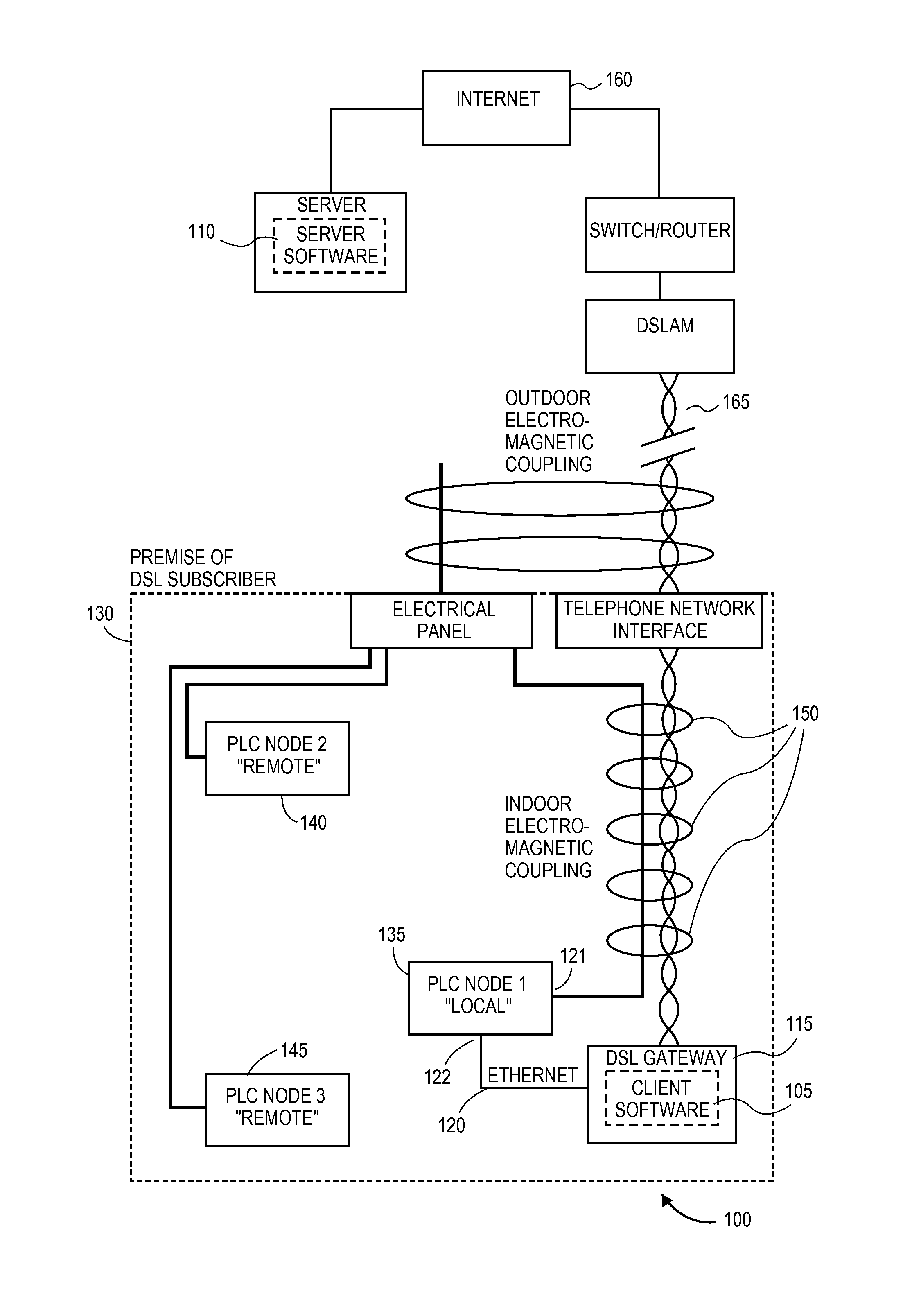
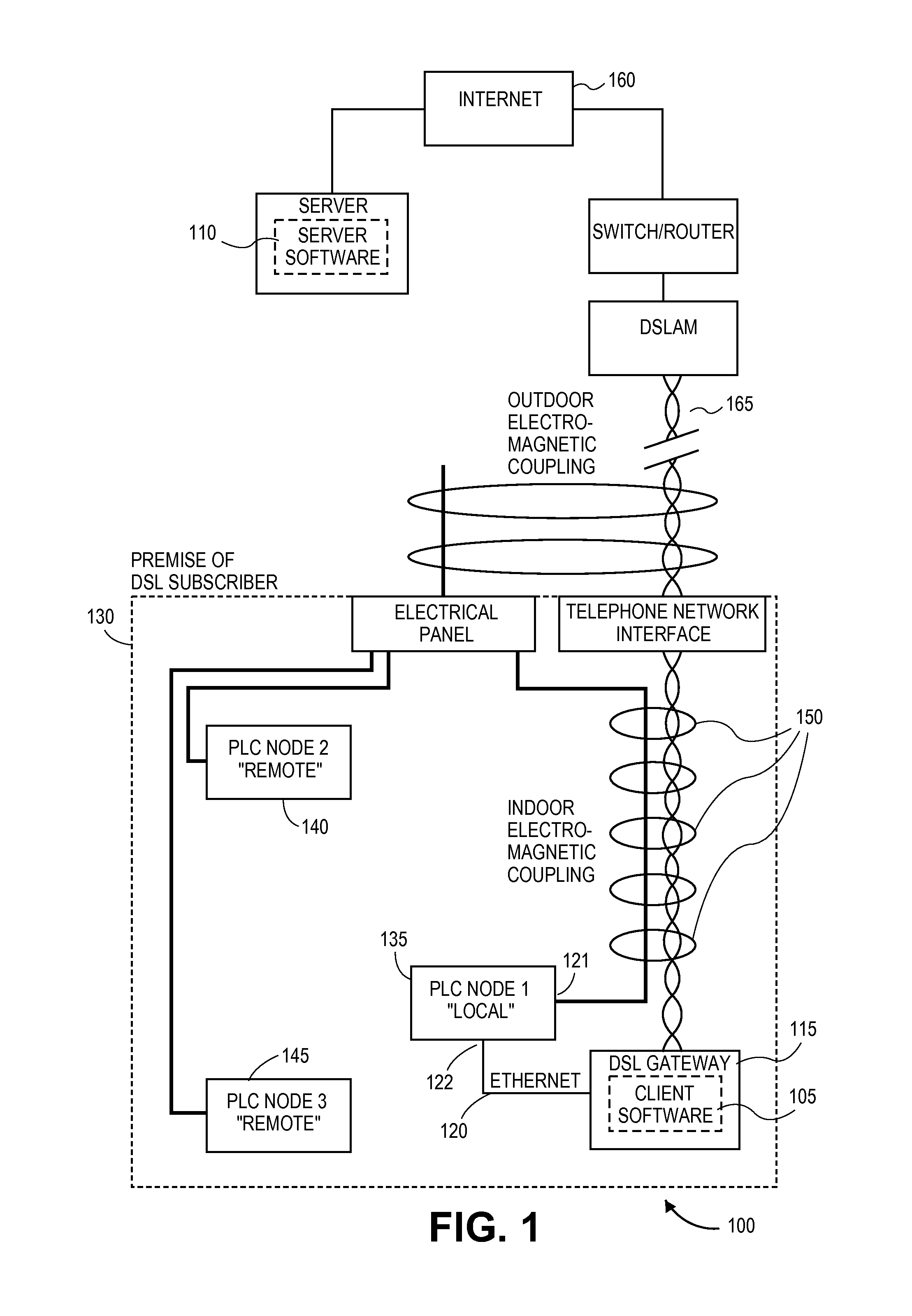
[0149]The Client 105 is a software module running in the host processor of the DSL gateway 115. Its actions are orchestrated by a Server 110, with which it communicates via the Internet 160, via the DSL connection 165 itself. There are three PLC nodes illustrated in FIG. 1, namely, nodes 135, 140 and 145. All employ the HomePlug AV protocol implemented on the Qualcomm Atheros '6400 chipset, in one embodiment. Node 1 (135) is the local PLC node, connected by Ethernet 120 to the DSL gateway 115. Nodes 2 (140) through N (145) are the remote PLC nodes.

Steps:

[0150]1. Choose vector DY>0. Calculate vector αY=10̂(DY / 10)−1.[0151]2. Ensure each PLC node's amplitude map is at factory default.[0152]3. Set n=1.[0153]4. Cause or wait for natural PLC traffic to become light.[0154]5. Measure vector SNRz.[0155]6. Cause PLC node 1 to transmit solo at duty cycle τa1, via the Forward method.[0156]7. Measure vector SNRa.[0157]8. Cease causing PLC node 1 to transmit.[0158]9. Calculate vector β1.[015...


PUM


Abstract

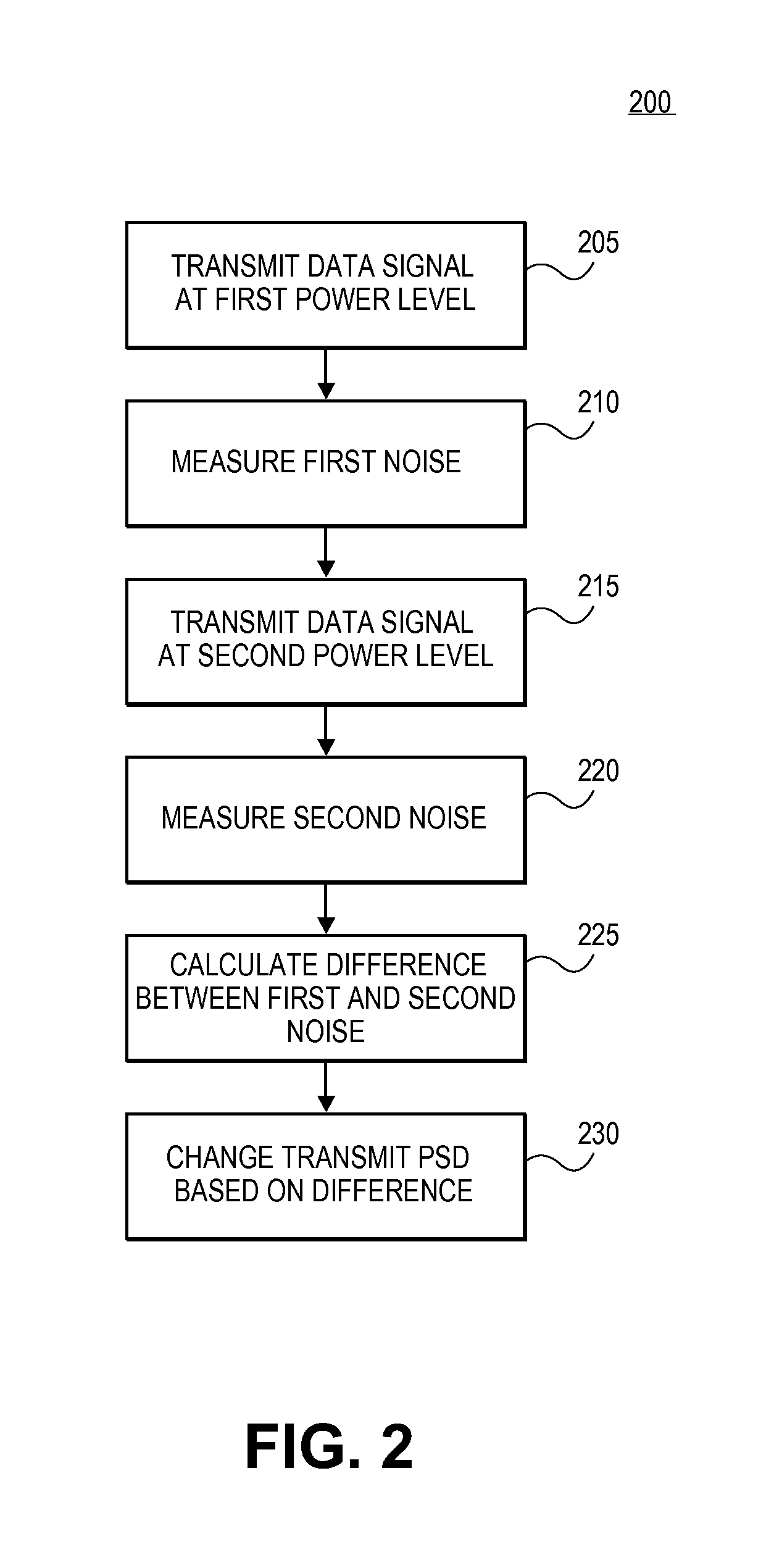
Reducing a power of a signal electromagnetically coupled from a PLC medium to a digital subscriber line (DSL) medium. The method involves transmitting a data signal over the PLC medium at a first average power level from one of a plurality of PLC transmitters coupled to the PLC medium, then measuring first noise associated with a first signal received at a DSL receiver coupled to the DSL communication medium caused at least in part by the data signal transmitted over the PLC medium at a second average power level from the one PLC transmitter, the second average power level different than the first average power level, followed by measuring second noise associated with a second signal received at the DSL receiver coupled to the DSL communication medium caused at least in part by the data signal transmission over the PLC medium at the second average power level. A transmit power spectral density (PSD) for the data signal transmitted by the one PLC transmitter over the PLC medium is then changed, based on a difference between the first noise and the second noise, such that the changed transmit PSD for the data signal transmitted by the one PLC transmitter over the PLC medium reduces the power of the signal electromagnetically coupled from the PLC medium to the DSL medium caused by the data signal transmission from the one PLC transmitter over the PLC medium.

Description

FIELD OF THE INVENTION[0001]The invention relates to Digital Subscriber Line technology. In particular, embodiments of the invention relate to an apparatus and method for reducing electromagnetic coupling from a power line communication (PLC) medium to a digital subscriber line (DSL) communication medium.BACKGROUND OF THE INVENTIONThe Phenomenon: Electromagnetic Coupling Between PLC and DSL[0002]We consider the case where the following statements are both true:[0003]A premise contains a point of termination for digital subscriber line (DSL), defined here as ITU G.993.1, ITU G.993.2, or a similar multi-tone-modulated protocol.[0004]The same premise employs power line communications (PLC), defined here as HomePlug AV, ITU G.hn, or a similar protocol, whose implementation provides a means for shaping the transmit power spectral density (PSD).[0005]The physical medium for DSL is typically voice-grade telephone cable or data-grade cable such as Cat5. The physical medium for PLC is typica...

Claims


Application Information

Patent Timeline
Patent Type & Authority Applications(United States)
IPC IPC(8): H04B3/54H04B17/00H04M11/06H04B3/32
CPCH04B3/54H04B3/32H04B2203/5425H04M11/06H04B2203/5495H04B17/0055H04B17/345H04M3/34H04M3/5166H04M11/062H04W52/225H04W52/346
Inventor PARNELL, ROBERT S.
Owner ASSIA SPE LLC CO THE CORP TRUST CO
Learn More