
Projector

a projector and projector technology, applied in the field of projectors, can solve the problems of increased noise, inability to correct dimming, and high rate of luminance change of picture, and achieve the effect of reducing noise and reducing heat load on the aperture member

Inactive Publication Date: 2014-12-18
SEIKO EPSON CORP
View PDF4 Cites 4 Cited by
  • Summary
  • Abstract
  • Description
  • Claims
  • Application Information

AI Technical Summary

Benefits of technology

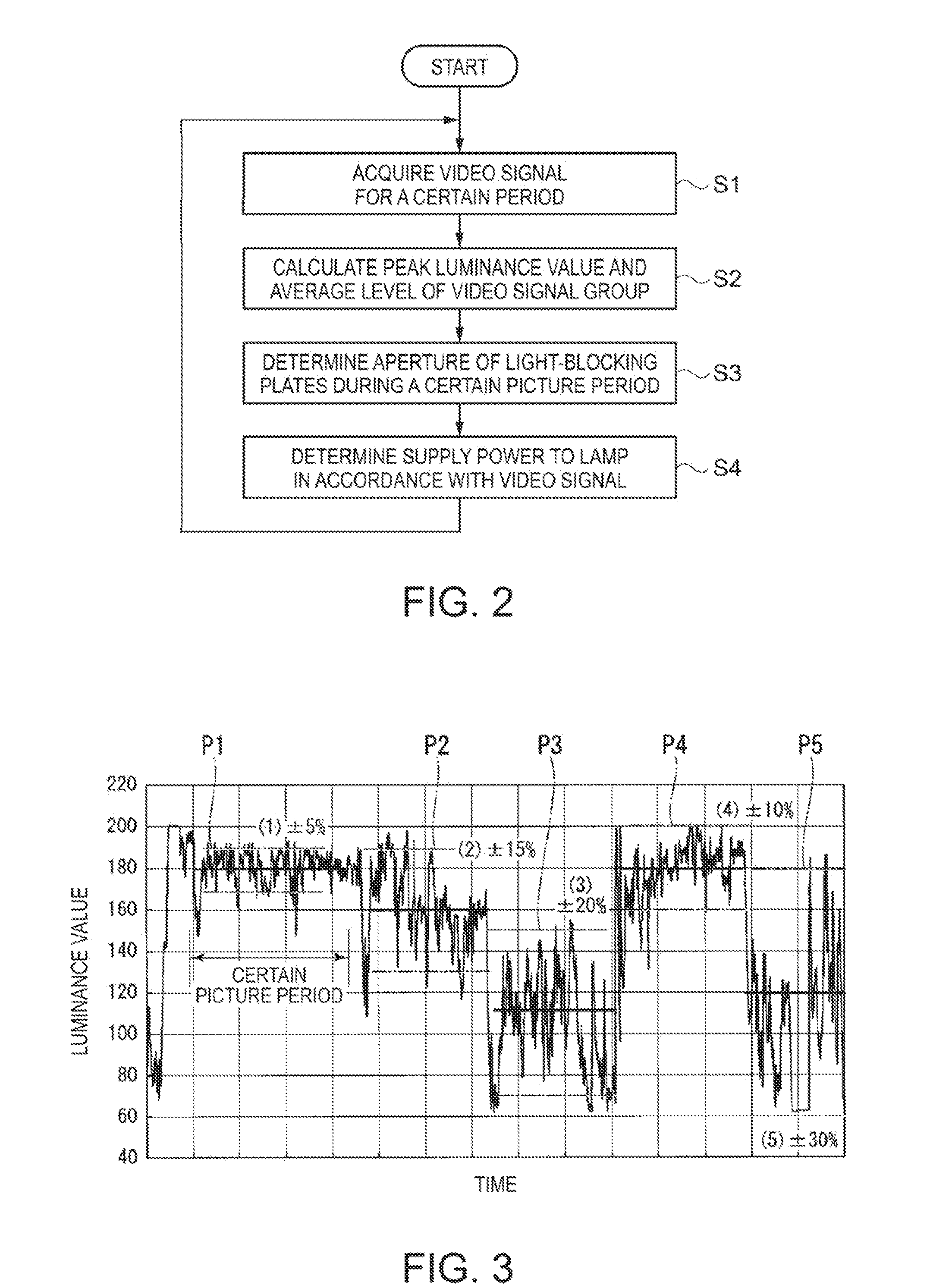
The invention aims to provide a projector that can dim the lighting according to the brightness of the picture being shown, while also reducing the noise caused by the dimming process. This is achieved by using both a mechanical dimming device and a light source dimming device. The aperture of the projector is fixed to a constant value during the picture period, and the power of the light source is adjusted to match the brightness of the picture. This improves the ability of the projector to follow the brightness changes of the picture, while reducing the noise caused by the dimming process. By controlling the aperture and power of the light source, the projector is able to adjust the amount of light emitted based on the brightness of the picture, while minimizing the amount of light blocked by the aperture. Overall, the invention improves the performance of the embedded projector in various lighting conditions.

Problems solved by technology

However, since there is a limitation in the operation speed of the light-blocking member, there is a problem that the light-blocking member cannot sufficiently follow the change in luminance, and thus correct dimming cannot be performed in the case in which the rate of the change in luminance of the picture is high.
Further, there is a problem that the noise is increased in the case in which the operation frequency of the light-blocking member is raised in accordance with the change in luminance of the picture.

Method used


Image

  • Projector
  • Projector
  • Projector

Examples


Embodiment Construction

[0020]Hereinafter, an embodiment of the invention will be explained with reference to the accompanying drawings.

[0021]The projector according to the present embodiment is an example of a projector provided with three sets of liquid crystal light valves as a light modulation device, namely a so-called three-chip liquid crystal display (3LCD) projector.

[0022]In the following drawings, the constituents might be shown with the respective scale ratios of the sizes different from each other in order to make the constituents eye-friendly.

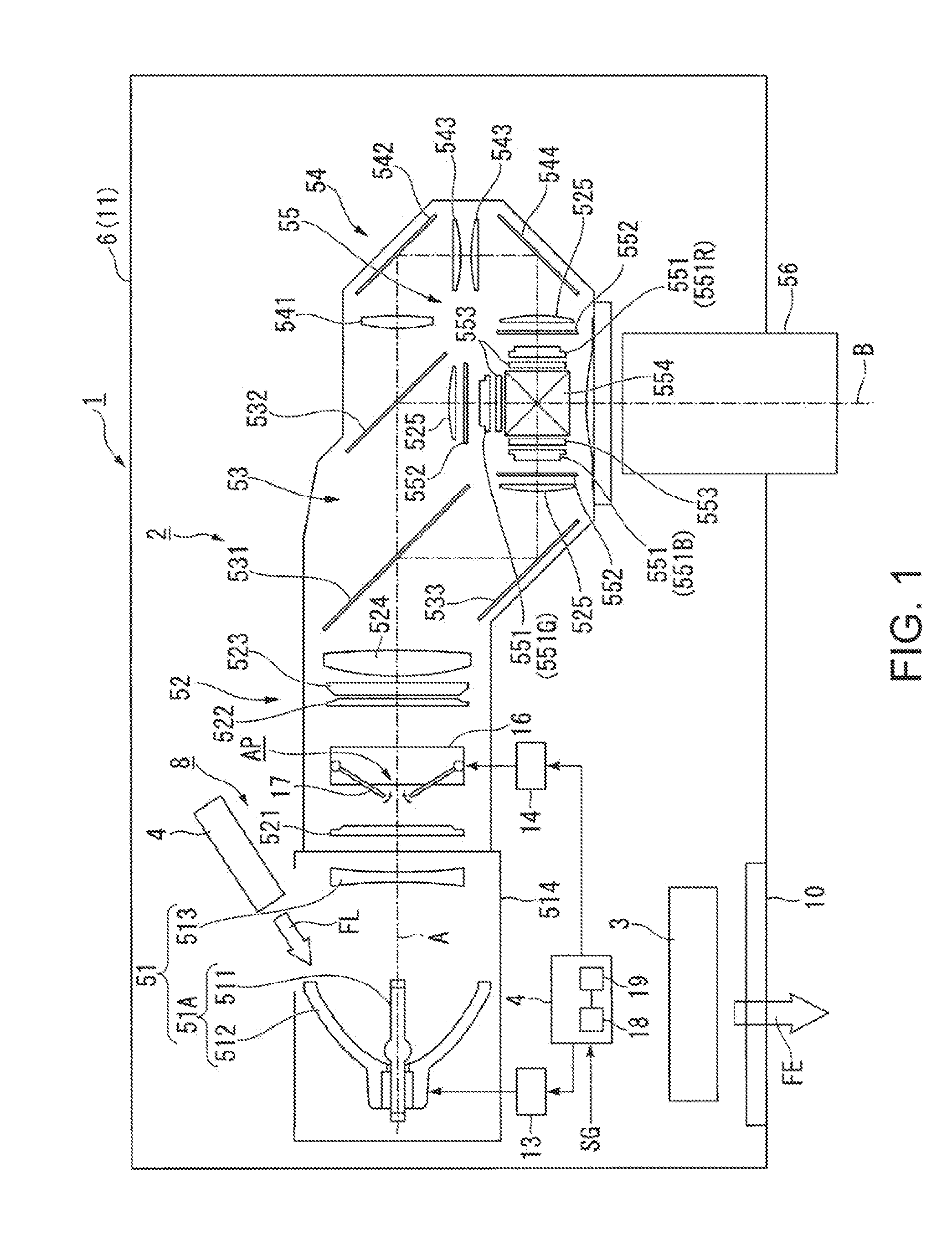
[0023]As shown in FIG. 1, the projector 1 according to the present embodiment is provided with an optical unit 2, an exhaust fan 3, a control section 4, and a housing 6. The control section 4 controls a ballast 13 and a light-blocking plate driving motor 14 described later. The optical unit 2 is provided with an illumination device 8, a color separation optical system 53, a light modulation device 55, a color combining optical element 554, and a projection...


PUM


Abstract

A projector includes a lamp, a ballast, an aperture member including light-blocking plates, a light-blocking plate driving motor, a control section, a light modulation device, and a projection optical system, and the control section controls the ballast and the light-blocking plate driving motor so as to modulate the lamp power based on a luminance of the video signal while fixing the aperture of the aperture member to a constant value in a picture period in accordance with a luminance parameter corresponding to a video signal group in the picture period among a series of the video signals.

Description

BACKGROUND[0001]1. Technical Field[0002]The present invention relates to a projector.[0003]2. Related Art[0004]In the past, there has been known a projector as one of display devices. The projector modulates light from, for example, an illumination device with a light modulation device to thereby form an image, and then projects the image on a screen with a projection optical system. In the projector, there has been proposed a technology for controlling the intensity of the light emitted from a light source with a dimming device to thereby improve the contrast of the image (see, e.g., JP-A-2010-243976 (Document 1) and JP-A-2010-211035 (Document 2)).[0005]In the projectors of Document 1 and Document 2, the dimming device is provided with a light-blocking member for blocking at least a part of the light from the light source. The light-blocking member moves into and out from a light path in between the light source and a light modulation device. The intensity of the light to be blocke...

Claims


Application Information

Patent Timeline
IPC IPC(8): H04N5/74
CPCH04N5/7416H04N9/3105H04N9/3155
Inventor SUGIYAMA, NOBUO
Owner SEIKO EPSON CORP
Learn More