
Trigger mechanism

a trigger mechanism and trigger technology, applied in the field of trigger mechanisms, can solve the problems of insufficient satisfaction of shooters, inability to repeat trigger pulls in semi-automatic mode of operation, and inability to achieve repeated trigger pulls

Active Publication Date: 2014-12-18
TAC CON DISTRIBUTION
View PDF4 Cites 22 Cited by
  • Summary
  • Abstract
  • Description
  • Claims
  • Application Information

AI Technical Summary

Benefits of technology

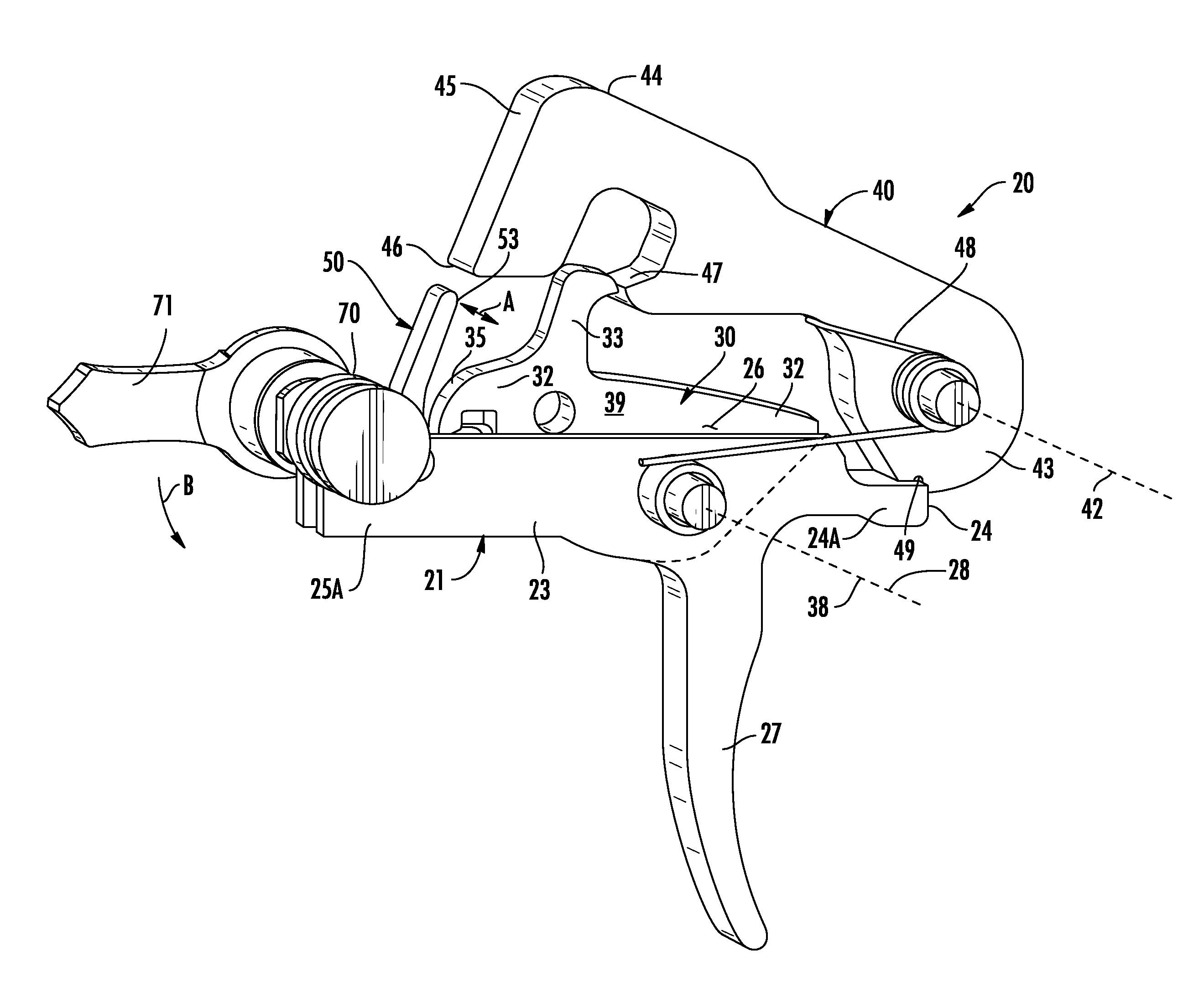
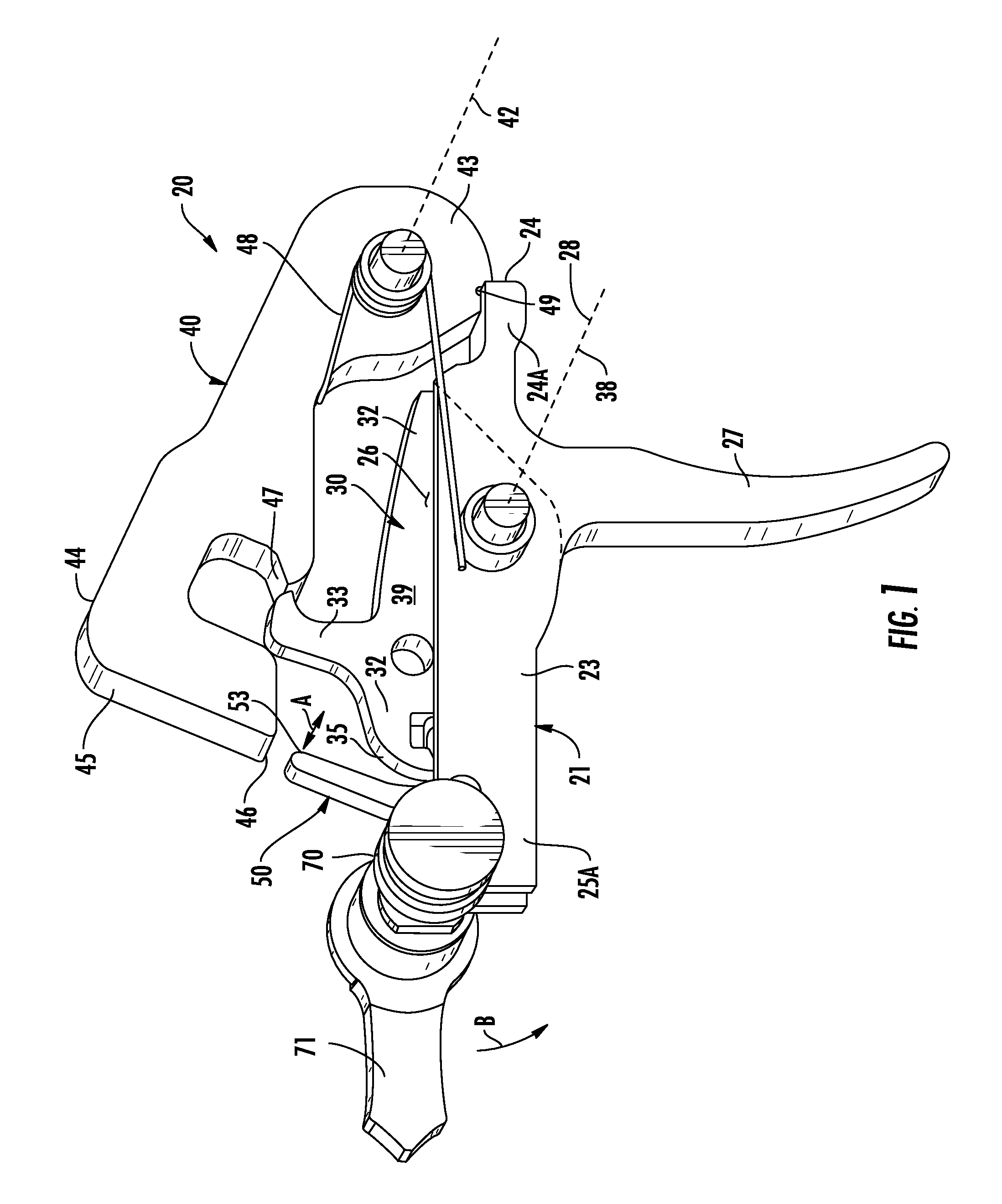
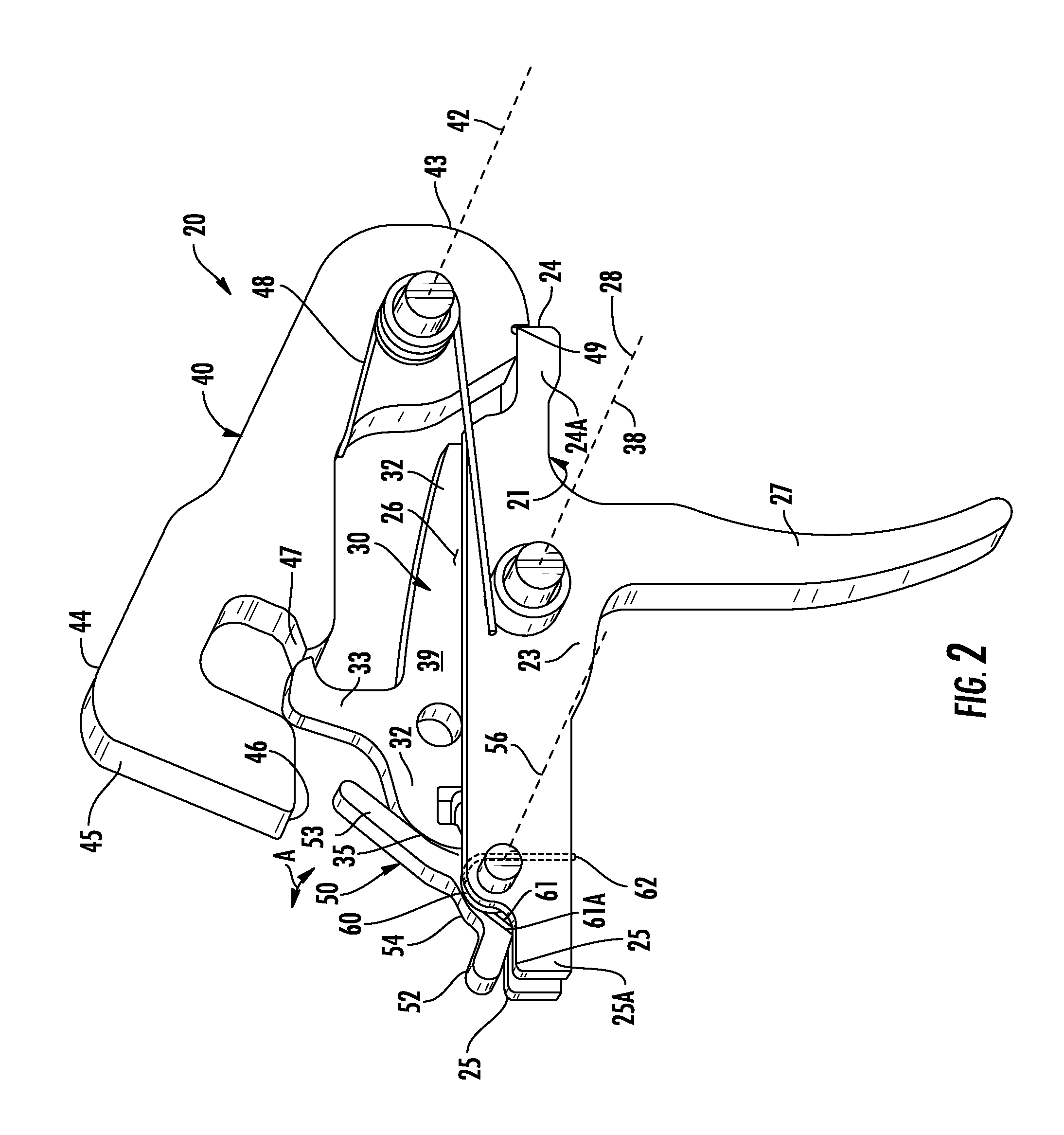
The invention is a trigger mechanism for firearms. The trigger mechanism includes a trigger disconnection assembly and a reset lever. When the hammer is pulled back and released, the trigger disconnection assembly moves from a discharged position to a charged position, where it engages the hammer and prepares to fire the firearm. The reset lever, which is pivoted between open and closed positions, isolates the hammer from the trigger disconnection assembly to prevent the hammer from hitting it. The hammer also has a trigger notch to receive the trigger nose when it is in the cocked position. This mechanism allows for safe and reliable operation of the firearm.

Problems solved by technology

In firearms limited to safe and semi-automatic modes of operation, one of the drawbacks to the trigger mechanism occurs when the hammer is returned to the cocked position by the bolt carrier.
After repeated firings of the weapon, this trigger snap can begin to cause bruising or other injury to the finger, making continued firing uncomfortable.
Another drawback to the trigger mechanism occurs after firing when the trigger nose resets into the trigger notch of the hammer to prevent forward motion of the hammer preparatory to firing by another trigger pull, where there is a substantial pause as the hammer travels rearwardly from the cocked position, to the past-cocked position, and then forwardly to the cocked position preparatory to firing by another trigger pull.
This pause inherently limits the speed of repeated trigger pulls in the semi-automatic mode of operation, which, for many competitive shooters, is not satisfactory.

Method used


Image

  • Trigger mechanism
  • Trigger mechanism
  • Trigger mechanism

Examples


Embodiment Construction

[0025]Known trigger mechanisms used with various semi-automatic firearms that fire a single round each time the trigger is pulled and that have select fire capabilities that permit selection between safe and semi-automatic modes of operation include a trigger assembly having a trigger, a hammer having a sear hook, a disconnector, and a sear assembly. Operation of such a mechanism is well known to those skilled in the art and will not be described in detail, other than to describe how, after firing, the hammer is pivoted rearwardly by the action of the bolt carrier. As the hammer is moved to a cocked position and beyond to a past-cocked position, from the cocked position the hammer disconnect notch clips past the disconnector hook of the disconnector and over-travels to the past-cocked position where the portion of the hammer having the sear hook strikes the disconnector which in turn imparts the energy from the striking hammer to a rear portion of the trigger assembly, causing the t...


PUM


Abstract

A trigger mechanism includes a hammer, and a trigger disconnector assembly including a trigger body having a trigger nose, and a disconnector having a disconnector hook. A reset lever is mounted for movement between open and closed positions. The trigger disconnector assembly is in mechanical communication with the reset lever. A striking end of the hammer strikes the reset lever in a past-cocked position of the hammer moving the reset lever from the open position to the closed position, the reset lever acting on the trigger disconnector assembly to reset the trigger body and the disconnector in the past-cocked position of the hammer in preparation for securing the hammer in a cocked position preparatory to firing by another trigger pull of the trigger body.

Description

FIELD OF THE INVENTION[0001]The present invention relates to trigger mechanisms.BACKGROUND OF THE INVENTION[0002]There are numerous trigger mechanisms capable of being locked in safe, semi-automatic, burst, and fully automatic operation. Different variations of rifles will allow some or all of the various modes of operation. Selector mechanisms have been developed for use with the trigger mechanisms to select between some or all of the various modes.[0003]In firearms limited to safe and semi-automatic modes of operation, one of the drawbacks to the trigger mechanism occurs when the hammer is returned to the cocked position by the bolt carrier. After firing a round, the bolt carrier moves rearwardly, contacting the hammer and pivoting the hammer backwards into the cocked position. This action results in the sear hook at the striking end of the hammer directly striking the hammer-receiving surface of the disconnector and transferring energy to an operator's finger upon the trigger in ...

Claims


Application Information

Patent Timeline
Patent Type & Authority Applications(United States)
IPC IPC(8): F41A19/10F41A19/14
CPCF41A19/14F41A19/10
Inventor STAKES, MICHAEL A.
Owner TAC CON DISTRIBUTION
Learn More