
Device and methods for transvascular tumor embolization with integrated flow regulation

a technology of flow regulation and device, applied in the field of medical methods and devices, can solve the problems of toxicity and complications, drop in pressure in the vascular space distal to partial occlusion, etc., and achieve the effects of reducing non-target embolization, preventing retrograde flow, and reducing the flow of hepatic arterials

Active Publication Date: 2014-12-11
EMBOLX
View PDF0 Cites 36 Cited by
  • Summary
  • Abstract
  • Description
  • Claims
  • Application Information

AI Technical Summary

Benefits of technology

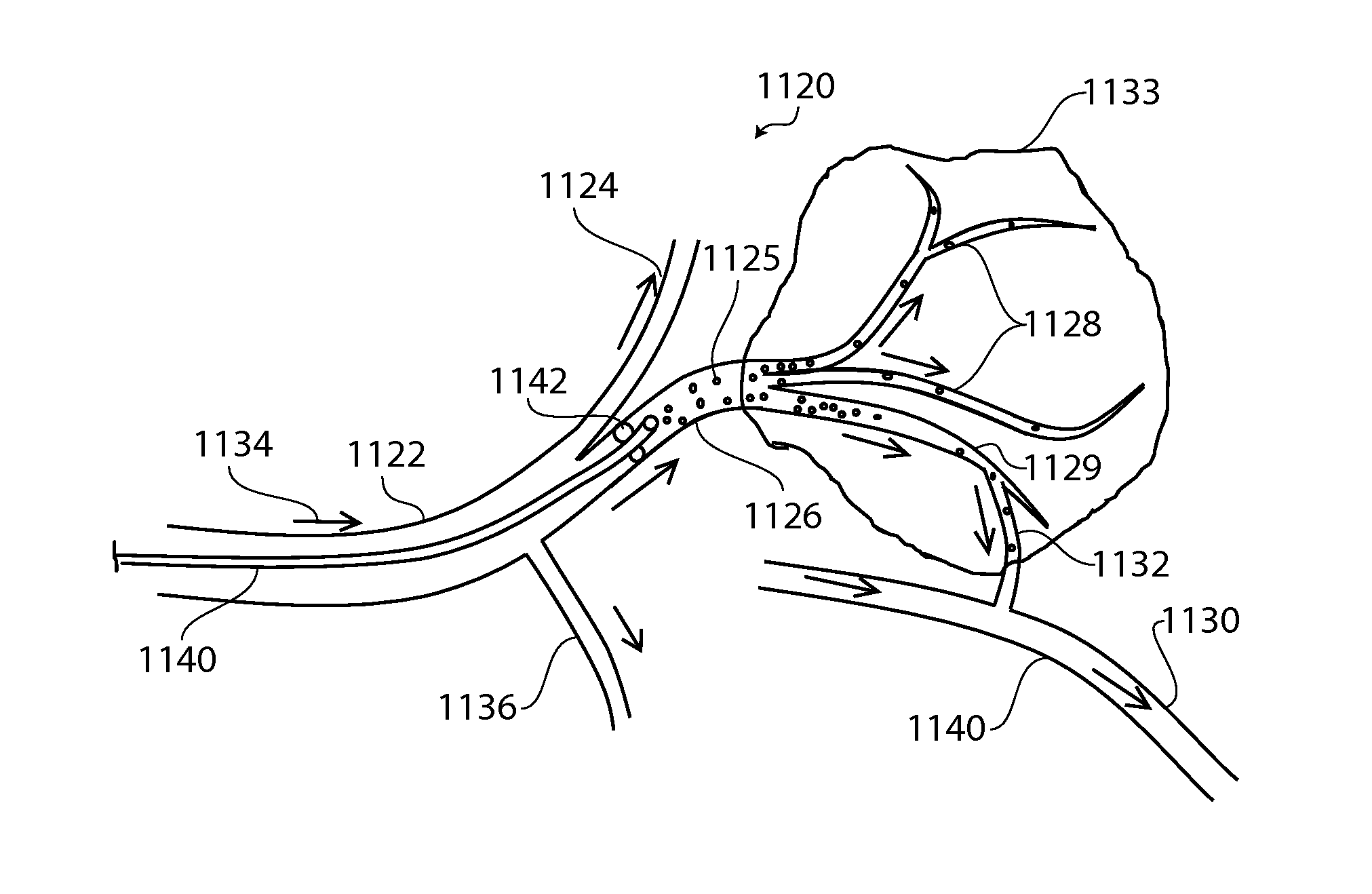
The present patent describes a method and device for delivering therapeutic agents to a target site within a body. The device includes a balloon with channels and valves that create a partial occlusion in the hepatic artery, reducing blood flow and pressure in the tumor. This results in the reversal of flow in the distal hepatoenteric arteries, preventing anterograde bypass and promoting the delivery of therapeutic agents to the tumor. The device also includes a balloon sheath that can deflect fluid pressure in either direction, allowing for controlled delivery of therapeutic agents. The technical effects of this invention include improved efficacy and standardization of the procedure.

Problems solved by technology

In some embodiments, the flow rate reduction results in a pressure drop in the vascular space distal to the partial occlusion.
In this instance, when using a standard straight catheter, injection of embolic agents from the distal tip of the catheter results in flow of embolic agents into both the tumor and side branch arteries causing anterograde bypass and non-target embolization of the liver and gastrointestinal tract, a situation that causes toxicity and complications.

Method used


Image

  • Device and methods for transvascular tumor embolization with integrated flow regulation
  • Device and methods for transvascular tumor embolization with integrated flow regulation
  • Device and methods for transvascular tumor embolization with integrated flow regulation

Examples


first embodiment

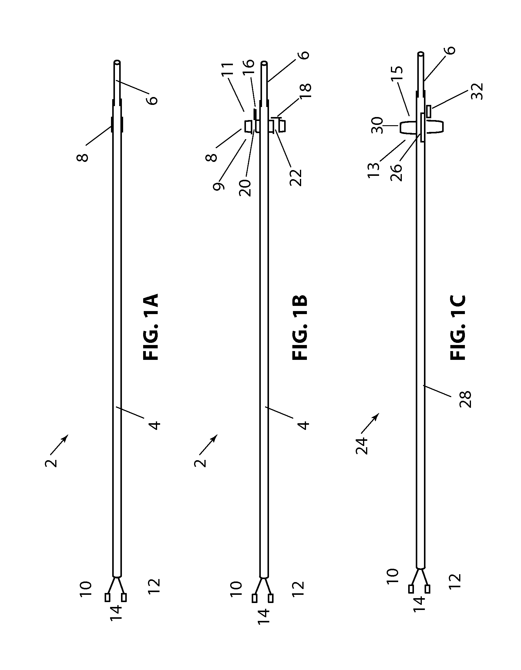
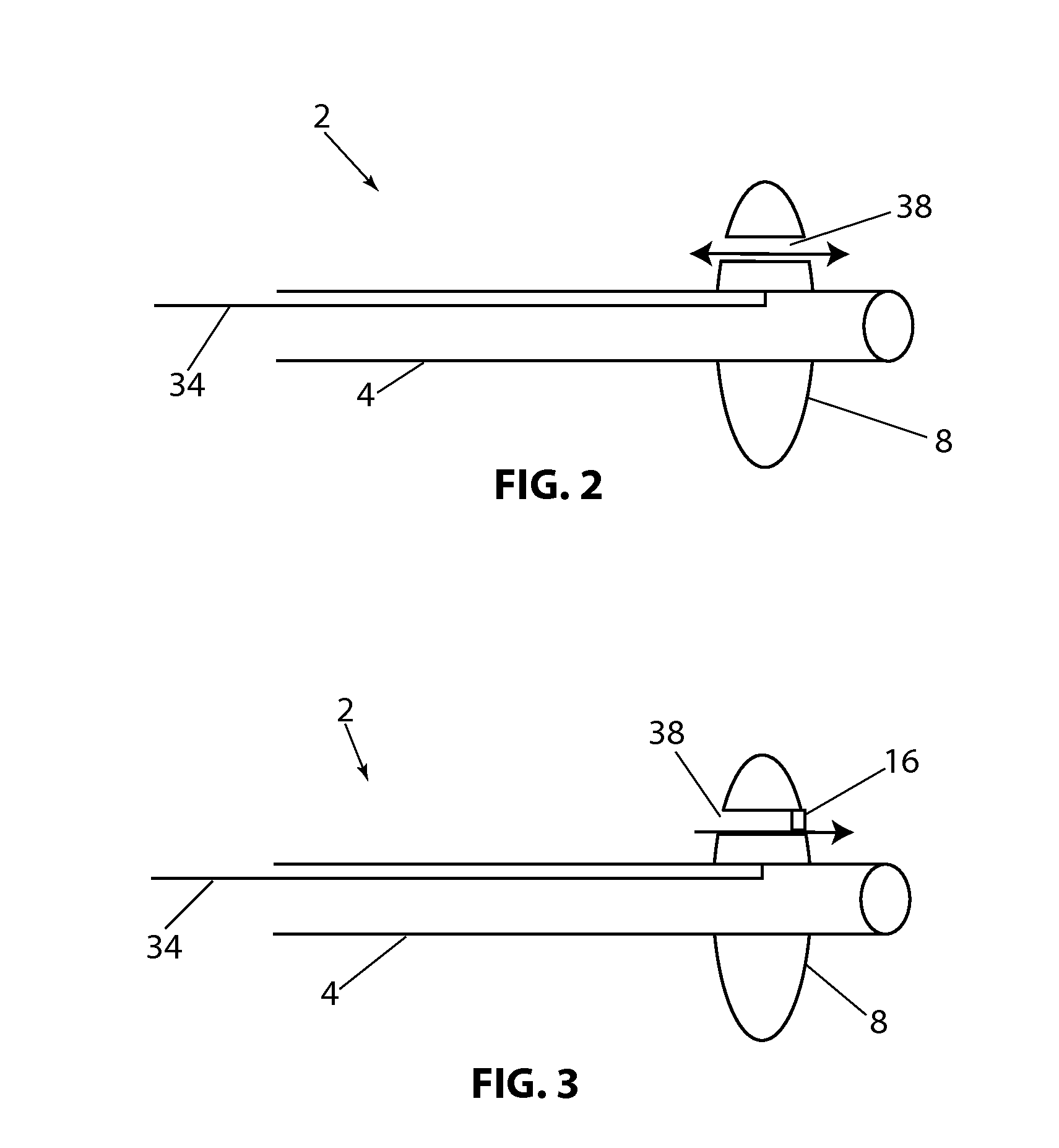
[0108]Referring to FIG. 1B, a longitudinal cross section of the present disclosure is shown, with device 2, balloon 8 (in the expanded configuration) having valve 16 in the open position and valve 18, in the closed position. In this embodiment flow channels 20 and 22 are constructed through balloon 8. Valves 16 and 18 allow fluid to flow in only one direction. Balloon 8 has a proximal side 9 and a distal side 11. By way of example, if fluid pressure is higher on the proximal side of balloon 8 and lower on the distal side of balloon 8, both valves 16&18 will open in response to the pressure difference and allow fluid to flow distally through the valves. If the pressure is higher on the distal side of balloon 8, valves 16 and 18 will close and prevent fluid from flowing proximally. Alternately, the valves can be position or constructed so that fluid can pass proximally and be prevented from flowing in the distal direction. Valves 16 and 18 are shown as a simple “flap” type valve, howe...

embodiment 135

[0139]Referring to FIG. 28A, a distal section of an alternate embodiment 135 of the present disclosure is shown with outer catheter 119, inner catheter 127, nose cone 125, radially constrained balloon 131 and catheter channels 123. The outer catheter 119 is adapted over inner catheter 121, the catheters configured to provide a radially distributed space between inner and outer catheters extending longitudinally along the length of device 135. Outer and inner catheters can have a length of 10 cm to 250 cm, more typically 50 cm to 150 cm and a diameter of between 0.5 Fr and 10 Fr more typically of 1 Fr to 5 Fr. Inner catheter 127 can have a length less than, equal to, or longer than the outer catheter 119, however in the present figure, inner catheter 127 is shown to be longer than outer catheter 119, its distal end forming the catheter extension 127. Nose cone 125 is disposed along the distal extension of inner catheter 127 at some distance from the distal end of outer catheter 119, ...


PUM


Abstract

A catheter assembly may be provided with a catheter body and an inflatable balloon. The catheter body has a proximal end, a distal end and a balloon inflation lumen. The inflatable balloon is attachable to the distal end of the catheter body. The balloon has an inner surface that at least partially defines an interior volume. The balloon is configured such that the interior volume can be in fluid communication with the inflation lumen of the catheter body to inflate the balloon. The balloon also has a proximal surface and a distal surface. The balloon is provided with a channel that extends through the balloon. The channel is configured to provide fluid communication between the proximal surface of the balloon and the distal surface of the balloon. Other catheter assemblies and methods of use are also disclosed.

Description

CROSS REFERENCE TO RELATED APPLICATIONS[0001]This application claims the benefit of U.S. Provisional Applications No. 61 / 821,058 filed May 8, 2013, No. 61 / 915,425 filed Dec. 12, 2013, and No. 61 / 917,131, filed Dec. 17, 2013, each of which is herein incorporated by reference in its entirety.INCORPORATION BY REFERENCE[0002]All publications and patent applications mentioned in this specification are herein incorporated by reference to the same extent as if each individual publication or patent application was specifically and individually indicated to be incorporated by reference.FIELD[0003]This application relates generally to medical methods and devices. More specifically, the present application discloses various embodiments of occlusion devices adapted to a catheter, and methods for their use in delivering fluids, embolic materials and other therapeutic agents to sites within the body.BACKGROUND[0004]There are over one million cases of cancer diagnosed each year in the United State...

Claims


Application Information

Patent Timeline
IPC IPC(8): A61M25/10A61M25/00
CPCA61M25/1025A61M25/0075A61M2025/0001A61M2025/1097A61M2025/1052A61M2025/109A61M2025/105A61B17/1204A61B17/12109A61M25/1002A61M2025/0003A61M2025/1081A61M2025/1093A61B17/12136A61M2005/1726A61M2025/0076A61B17/12A61M5/172A61M25/00A61M5/1723A61M2025/0002A61M2210/12A61M5/16804A61M25/0068A61M25/0069A61M25/10A61M2025/1061
Inventor ALLEN, MICHAEL P.BROMMER, ROBERT A.HANNON, TREVOR M.DE NEVE, ROBERT
Owner EMBOLX
Learn More