Short-circuit protection structure

Inactive Publication Date: 2014-12-11
SUZHOU POWERON IC DESIGN
View PDF5 Cites 0 Cited by
  • Summary
  • Abstract
  • Description
  • Claims
  • Application Information

AI Technical Summary

Benefits of technology

The present invention provides a short-circuit protection structure for a switching power supply system with high reliability and low cost. The structure prevents damage to the system or chip due to short-circuiting of the current sampling resistors. The short-circuit protection device can detect a short-circuit signal and latch the chip off, improving the reliability and reducing the failure rate of the chip. The power supply chip with the short-circuit protection structure has improved product reliability and reduced failure ratio of production. The short-circuit protection structure is simple and cost-effective, with no need for additional system components.

Problems solved by technology

However, when the sampling resistor Rs1 is not integrated with the control circuit 1 or the output stage transistor 2, short circuiting of the sampling resistor Rs1 that occurs during the actual production process is inevitable, and the short circuiting may be due to solder bridging, broken resistors, PCB bridging, short circuiting of pins of the chip and so on.
When the Rs1 is shorted, the resistance of Rs1 gets so small that the voltage Vs1 will not be able to reach the reference voltage Vref1 of the internal comparator, and the over-current protection for the output stage transistor by the control circuit will be a failure, the output stage transistor will work at the maximum duty cycle, and the output stage transistor will work in the saturation region (high Vds and large Ids) which is beyond its safe operating area, resulting in breakdown of the output stage transistor even resulting in damage of the whole system. FIG. 2 shows signal waveforms of the traditional switching mode power supply without short-circuit protection when the sampling resistor is shorted.

Method used


Image

  • Short-circuit protection structure
  • Short-circuit protection structure
  • Short-circuit protection structure

Examples


first embodiment

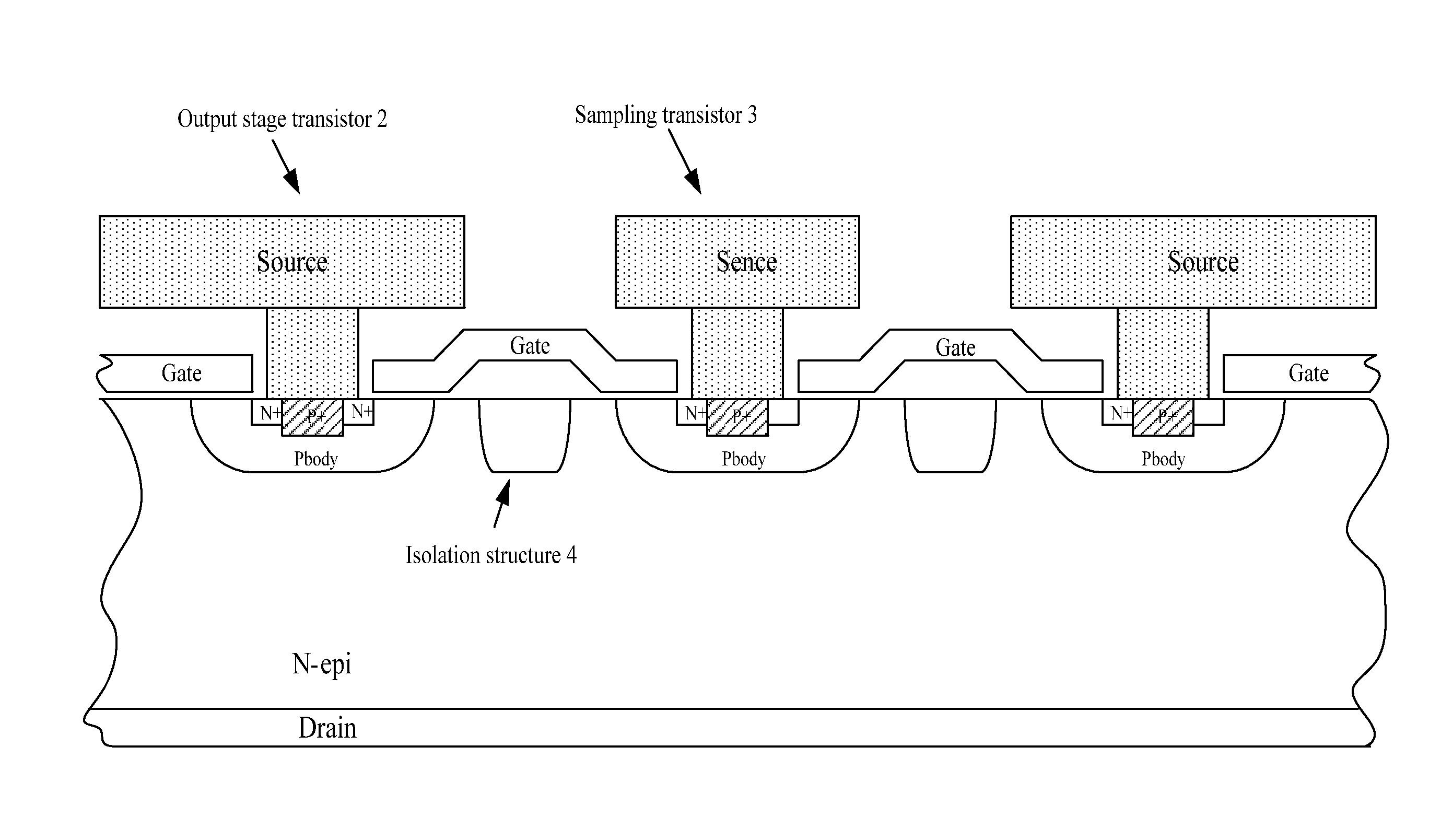
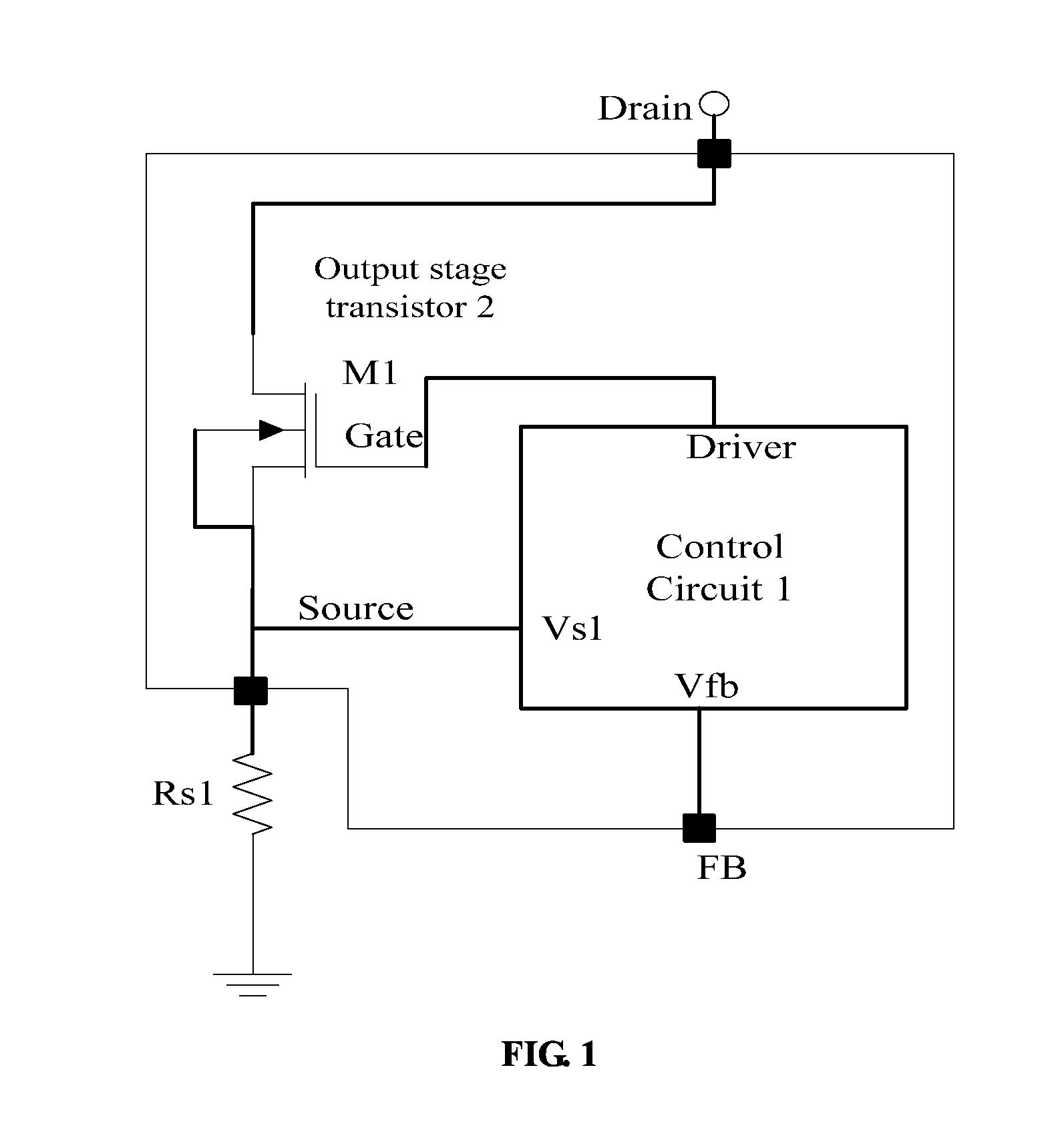
[0043]The integration solution of the first embodiment is that a vertical output stage transistor is integrated with the control circuit. When the vertical output stage transistor is integrated, the sampling transistor is provided on said vertical output stage transistor, as shown in FIG. 6. The structure of the sampling transistor 3 is the same as the structure of the output stage transistor 2, in order that the current factor K between the sampling transistor 3 and the output stage transistor 2 is a constant. As shown in FIG. 7, a vertical sectional diagram illustrating the structure of said vertical transistor, the structure of primitive cells of the sampling transistor 3 is the same as that of the output stage transistor 2, and an isolation structure 4 is provided between the output stage transistor 2 and the sampling transistor 3 to prevent the current factor K from drifting due to electric leakage between the two transistors.

second embodiment

[0044]The integration solution of the second embodiment is that a lateral output stage transistor is integrated with the control circuit. When the lateral output stage transistor is integrated, the sampling transistor 3 is provided on said lateral output stage transistor, as shown in FIG. 8. The structure of the sampling transistor 3 is the same as the structure of the output stage transistor 2, in order that the current factor K between the sampling transistor 3 and the output stage transistor 2 is a constant.

[0045]The integration solution of the third embodiment is that the output stage transistor is not integrated with the control circuit. The output stage transistor is an independent and discrete component, which can be either a lateral voltage withstand transistor or a vertical voltage withstand transistor. As shown in Figure in 9, the control circuit, the sampling transistor 3 (M2) and the second current sampling resistor (Rs2) for the sampling transistor are integrated togeth...


PUM


Abstract

A short-circuit protection structure comprises first and second high-voltage transistors, a control circuit, a first current sampling resistor for the first transistor and a second current sampling resistor for the second transistor. The control circuit controls switching period and duty cycle of the first transistor and the second transistor, a drain terminal of the first transistor is connected to a drain terminal of the second transistor, a source terminal of the first transistor is connected to the first current sampling resistor, and a source terminal of the second transistor is connected to the second current sampling resistor; a gate terminal of the first transistor and a gate terminal of the second transistor are connected to a driver stage of the control circuit. The size of the second transistor is smaller than the first transistor, and the current of the first transistor is sampled by the second transistor.

Description

CROSS-REFERENCE TO RELATED APPLICATIONS[0001]The present invention claims priority from Chinese Patent Application Ser. No. 201310230700.5 filed Jun. 9, 2013, which is incorporated herein by reference for all purposes.FIELD OF THE INVENTION[0002]The present invention relates to a short-circuit protection structure applicable to integrated circuits for power management, and belongs to the technical field of power semiconductor.BACKGROUND OF THE INVENTION[0003]As shown in FIG. 1, the traditional structure of the switching mode power supply comprises a control circuit 1 and an output stage transistor 2. Said control circuit 1 obtains the voltage Vs1 of a sampling resistor Rs1 and the system-level feedback signal Vfb, and controls the switching time and the duty cycle of said output stage transistor 2 by adopting an internal-loop algorithm, so as to realize the stable voltage output and current output of the system. No matter whether the output stage transistor 2 and control circuit 1 a...

Claims


Application Information

Patent Timeline
IPC IPC(8): H02H3/08
CPCH02H3/08H02H3/087H02H9/025H03K17/0822
Inventor TAO, PINGLI, HAISONGZHUANG, HUALONGYI, YANGBO
Owner SUZHOU POWERON IC DESIGN
Why Eureka
Try Eureka