
Power system stabilization

a power system and stabilization technology, applied in the direction of power oscillation reduction/prevention, adaptive control, instruments, etc., can solve the problems of multi-mode oscillation, power system stability becomes an important issue, and power system power oscillations

Active Publication Date: 2014-12-04
GENERAL ELECTRIC CO
View PDF6 Cites 12 Cited by
  • Summary
  • Abstract
  • Description
  • Claims
  • Application Information

AI Technical Summary

Benefits of technology

The patent text describes a method for reducing power system oscillations in a network. The method involves collecting measurement signals from various locations and using these signals to generate a control signal to compensate for the different modes of oscillation in the power system. The control signal is then injected into the power system to dampen the oscillations. The technical effect of this method is to improve the stability and efficiency of power systems and reduce the likelihood of oscillations that can cause damage or malfunctions.

Problems solved by technology

Since stressed conditions can lead a system to unstable conditions, power system stability has become an important issue.
The disturbance may be a fault, a loss of a generator or even a sudden increase in power loading which results in power oscillations in power system.
Small signal stability is a power system stability issue related to low frequency oscillations between generator rotors.
When the power system is heavily loaded, it often exhibits multi-mode oscillations because machine rotors, behaving as rigid bodies, oscillate with respect to one another using the electrical transmission lines between them to exchange energy.
However, lack of availability of accurate and updated information about each and every dynamic component of a large inter-connected system and its ever changing nature often puts a fundamental challenge on such model based approaches.
However, present architectures of indirect adaptive controllers utilize complex multi-input multi-output (MIMO) structure.
This leads to a multivariable controller, which is very complicated in nature.

Method used


Image

  • Power system stabilization
  • Power system stabilization
  • Power system stabilization

Examples


Embodiment Construction

[0014]As used herein, the term “controller” refers to software, hardware, or firmware, or any combination of these, or any system, process, or functionality that performs or facilitates the processes described herein.

[0015]When introducing elements of various embodiments of the present invention, the articles “a,”“an,”“the,” and “said” are intended to mean that there are one or more of the elements. The terms “comprising,”“including,” and “having” are intended to be inclusive and mean that there may be additional elements other than the listed elements.

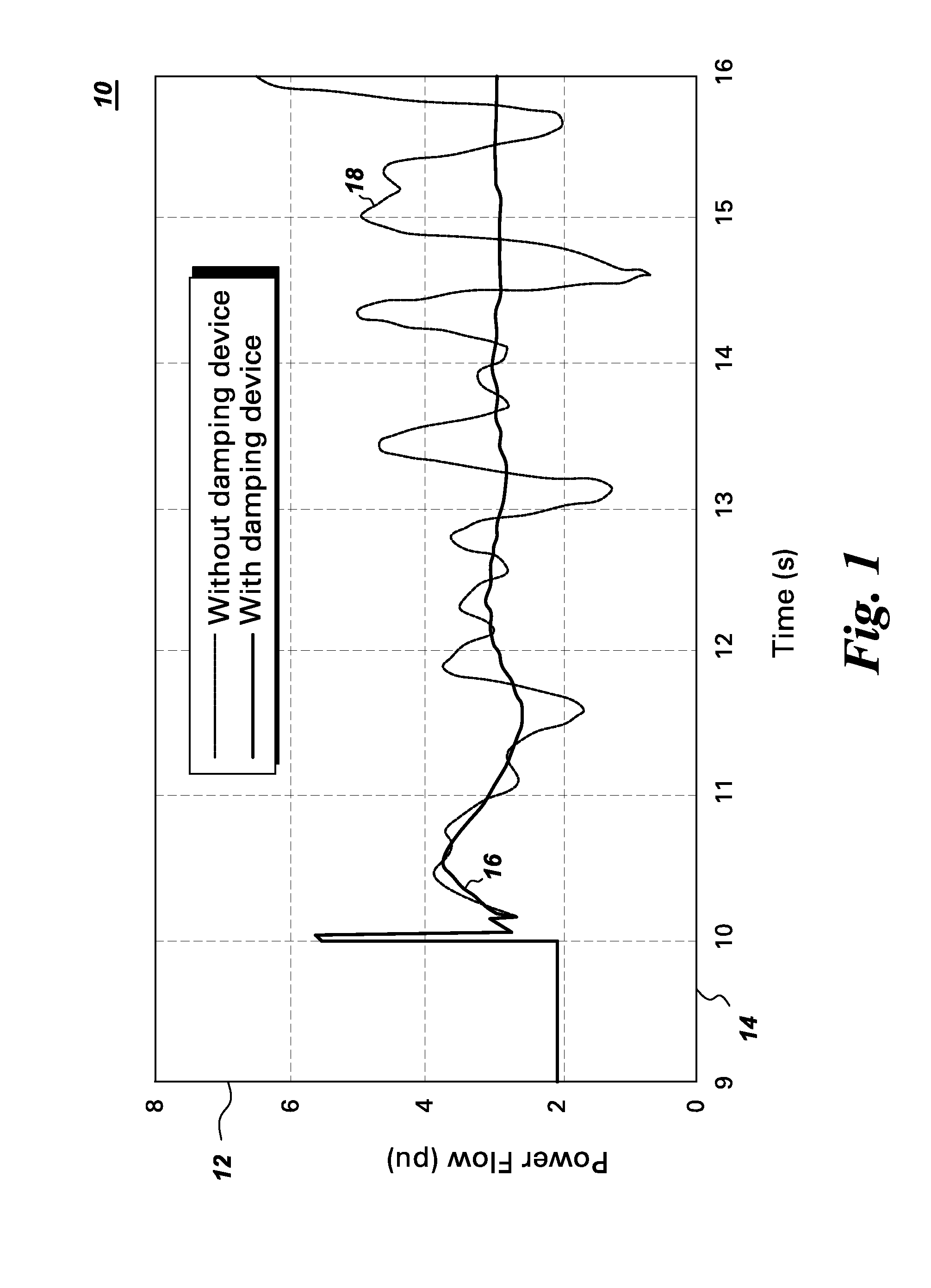
[0016]FIG. 1 shows a graphical plot 10 of exemplary power oscillations in a power system. A horizontal axis 14 represents time in seconds whereas a vertical axis 12 represents power flow in a transmission line in per unit (pu). A curve 18 shows power oscillations in the transmission line power flow without a damping controller. Even though only power oscillations are shown here, it should be noted that the oscillations may be present ...


PUM


Abstract

A system for damping power system oscillation includes a damping device controller for generating a damping control signal to compensate for a plurality of oscillation modes in the power system oscillations and a damping device to generate a damping signal based on a damping control signal. The damping device controller includes a plurality of outer closed loop paths each including an adaptive controller configured to determine an individual oscillation mode from at least one power system measurement signal. Each adaptive controller is further configured to generate an adaptive control signal to shift at least one open loop pole of an inner loop path related to the individual oscillation mode to a closed loop location.

Description

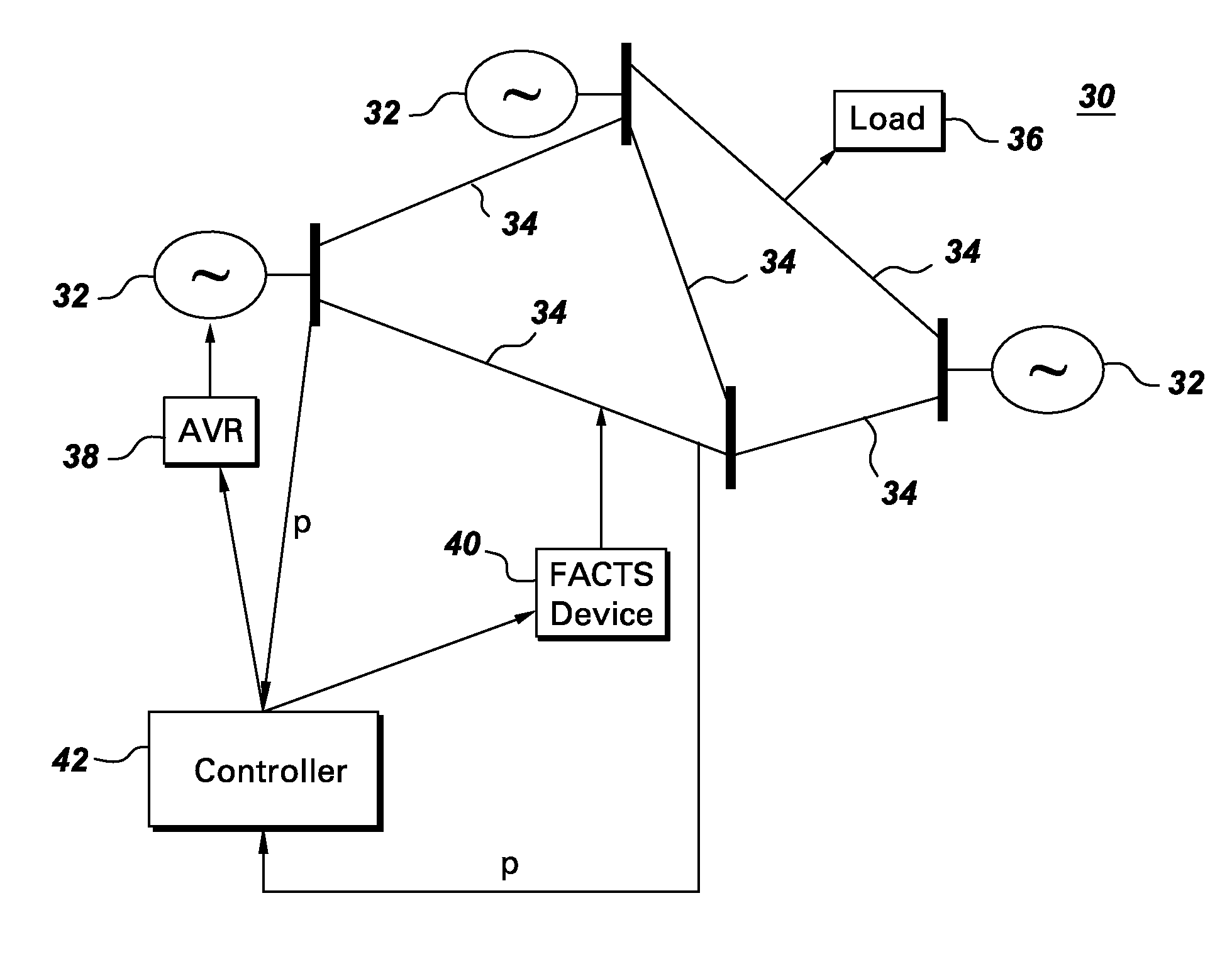
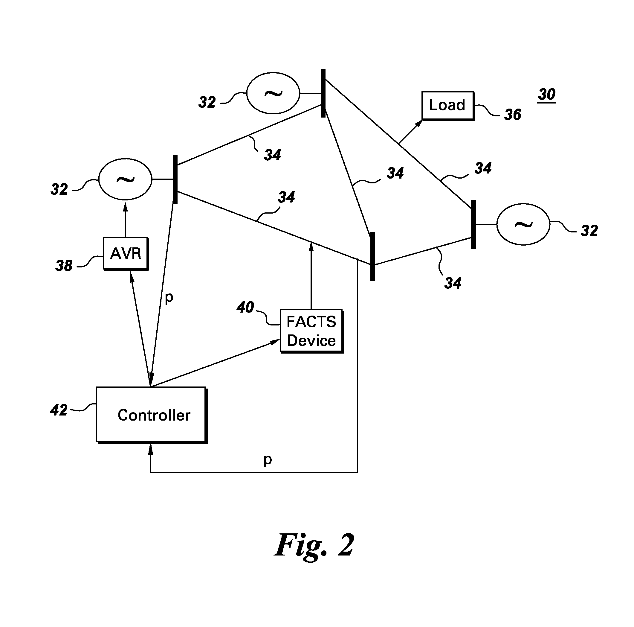
BACKGROUND[0001]Embodiments of the present invention relate generally to a power flow in a power system. More specifically, the embodiments relate to damping of power system oscillations.[0002]The power system is a complex network comprising of numerous generators, transmission lines, a variety of loads and transformers. With increasing power demand in the power system, some transmission lines are more stressed than was planned when they were built. Since stressed conditions can lead a system to unstable conditions, power system stability has become an important issue. In simple terms, power system stability is defined as the ability of the power system to return to a normal state after a disturbance. The disturbance may be a fault, a loss of a generator or even a sudden increase in power loading which results in power oscillations in power system.[0003]Small signal stability is a power system stability issue related to low frequency oscillations between generator rotors. It has bee...

Claims


Application Information

Patent Timeline
IPC IPC(8): H02J3/24
CPCH02J3/24G05B13/021H02J3/241
Inventor CHAUDHURI, NILANJAN RAY
Owner GENERAL ELECTRIC CO
Learn More