Antenna apparatus and feeding structure thereof
a technology of antenna apparatus and feeding structure, which is applied in the direction of antennas, antenna earthings, antenna details, etc., can solve the problems of difficult to improve the operation efficiency of the antenna apparatus without enlarging the size of the antenna apparatus, and the operation efficiency of the antenna apparatus may be deteriorated, so as to improve reduce the reflection coefficient. , the effect of improving the operation efficiency of the antenna apparatus
- Summary
- Abstract
- Description
- Claims
- Application Information
AI Technical Summary
Benefits of technology
Problems solved by technology
Method used
Image
Examples
first embodiment
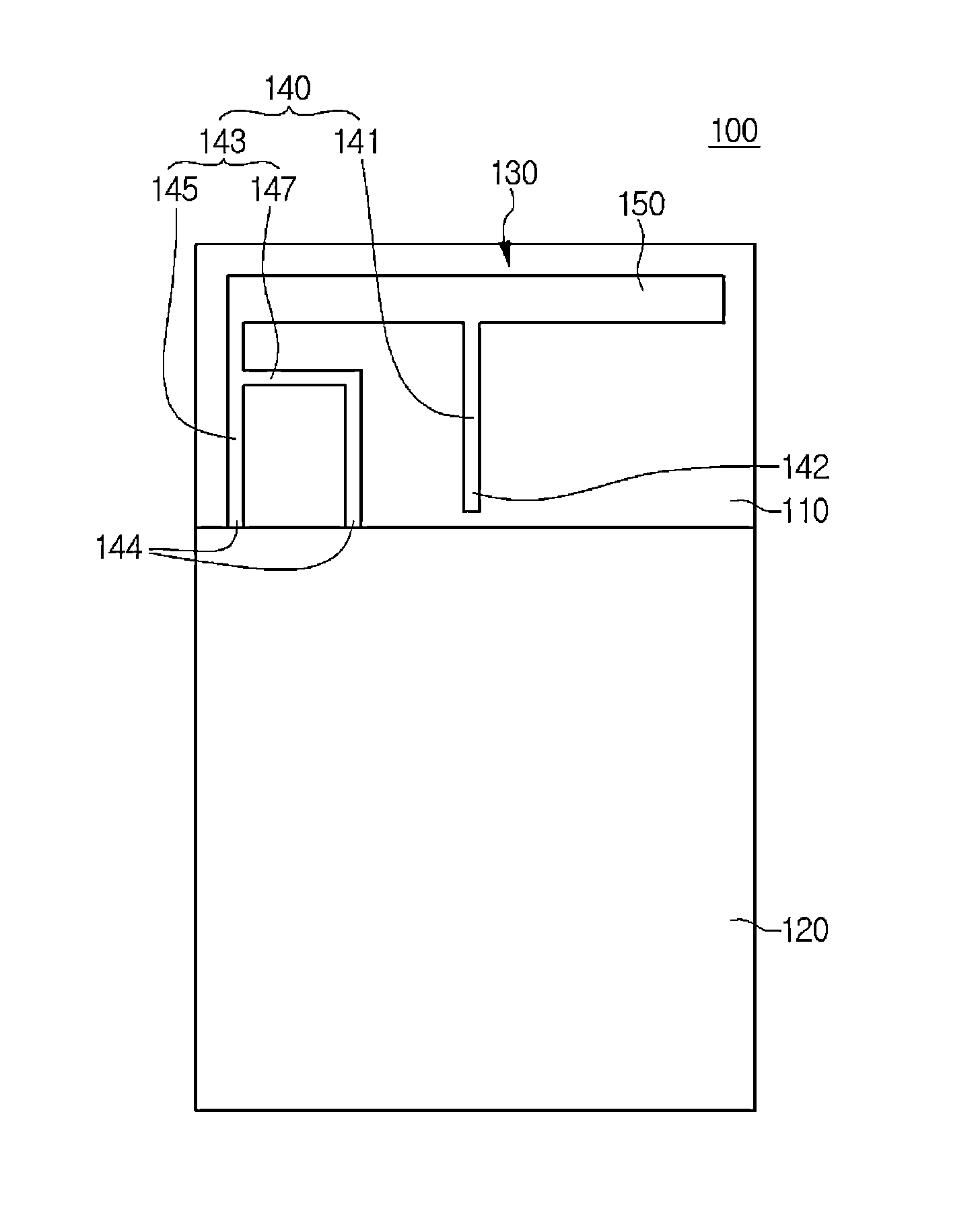
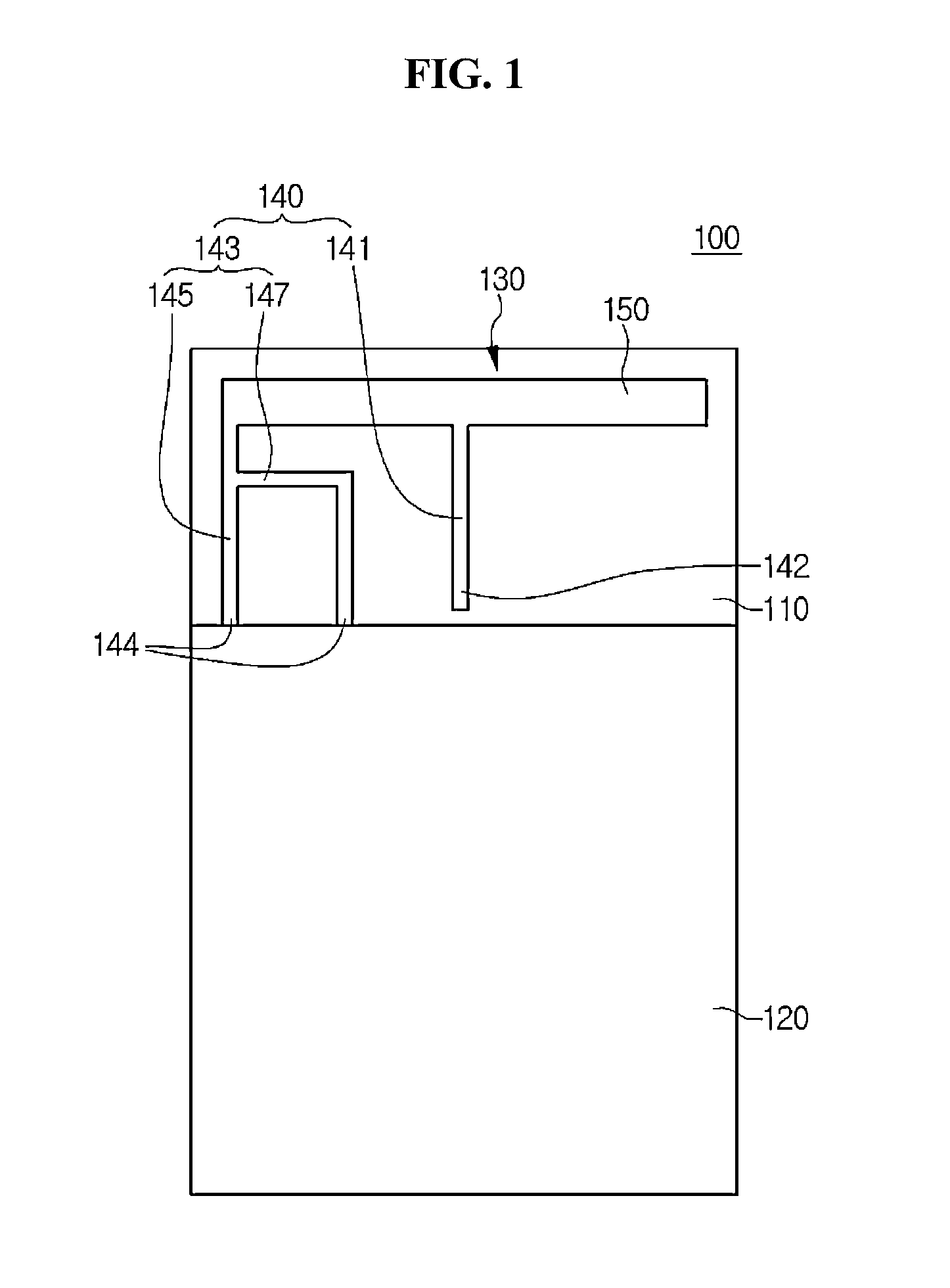
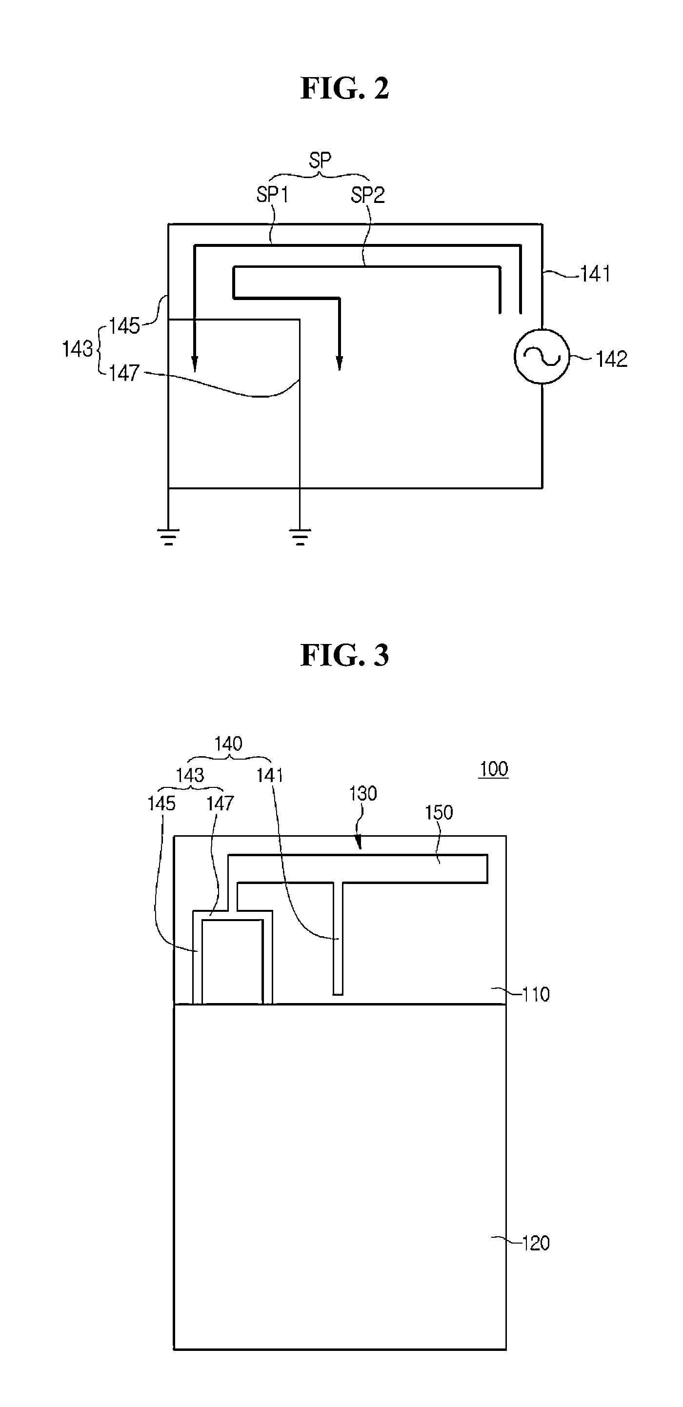
[0024]FIG. 1 is a plane view showing an antenna apparatus according to the FIG. 2 is a circuit diagram showing an equivalent circuit of a feeding structure in FIG. 1.
[0025]Referring to FIG. 1, the antenna apparatus 100 according to the embodiment include a drive substrate 110, a ground member 120 and an antenna element 130.
[0026]The drive substrate 110 serves as a power feeder and a supporter in the antenna apparatus 100. The drive substrate 110 has a flat plate structure. In this case, the drive substrate 110 may include a printed circuit board (PCB). The drive substrate 110 may be prepared as a single substrate, and may be prepared by laminating a plurality of substrates.
[0027]Further, a transmission line (not shown) is embedded in the drive substrate 110. The transmission line is connected to a control module (not shown) through one end thereof. In addition, the transmission line is exposed through the other end thereof. That is, the transmission line receives a signal from the ...
second embodiment
[0052]FIG. 6 is a plane view showing an antenna apparatus according to the FIG. 7 is a circuit diagram showing an equivalent circuit of a feeding structure in FIG. 6.
[0053]Referring to FIG. 6, the antenna apparatus 200 according to the embodiment include a drive substrate 210, a ground member 220 and an antenna element 230. In addition, the antenna element 230 includes a feeding structure 240 and a radiator 250. Since the configurations of the embodiment are similar to those of the above-described embodiment, the detail descriptions will be omitted.
[0054]Only, the feeding structure 240 of the embodiment includes a plurality of feeding units 241 and a ground unit 247.
[0055]The feeding units 241 provide a signal to the feeding structure 240. The feeding units 241 make contact with a transmission line through one ends thereof. In this case, the one ends of the feeding units 241 are defined as a feeding point (FP) 242. For example, the feeding point 242 may make contact with the transm...
third embodiment
[0066]FIG. 10 is a plane view showing an antenna apparatus according to the FIG. 11 is a circuit diagram showing an equivalent circuit of a feeding structure in FIG. 10.
[0067]Referring to FIG. 10, the antenna apparatus 300 according to the embodiment include a drive substrate 310, a ground member 320 and an antenna element 330. In addition, the antenna element 330 includes a feeding structure 340 and a radiator 350. Since the configurations of the embodiment are similar to those of the above-described embodiment, the detail descriptions will be omitted.
[0068]Only, the feeding structure 340 of the embodiment includes a plurality of feeding units 341 and a plurality of ground units 347.
[0069]The feeding units 341 provide a signal to the feeding structure 340. The feeding units 341 make contact with a transmission line through one ends thereof. In this case, the one ends of the feeding units 341 are defined as a feeding point (FP) 342. For example, the feeding point 342 may make conta...
PUM
 Abstract
Description
Claims
Application Information
 - R&D
- Intellectual Property
- Life Sciences
- Materials
- Tech Scout
- Unparalleled Data Quality
- Higher Quality Content
- 60% Fewer Hallucinations
Browse by: Latest US Patents, China's latest patents, Technical Efficacy Thesaurus, Application Domain, Technology Topic, Popular Technical Reports.
© 2025 PatSnap. All rights reserved.Legal|Privacy policy|Modern Slavery Act Transparency Statement|Sitemap|About US| Contact US: help@patsnap.com


