Optical element

a technology of optical elements and photovoltaic materials, applied in the direction of solar radiation concentration, sustainable buildings, lighting and heating apparatus, etc., can solve the problems of low efficiency of photovoltaic materials, less than 20% of the cost of photovoltaic materials generally contributing to the overall cost of the system. achieve the effect of improving detection sensitivity

Active Publication Date: 2014-11-27
UNIV COURT OF GLASGOW CALEDONIAN UNIV
View PDF1 Cites 4 Cited by
  • Summary
  • Abstract
  • Description
  • Claims
  • Application Information

AI Technical Summary

Benefits of technology

[0072]In this way, the radiation concentrating properties of the optical element may be used to increase the radiation received by the sensor or detector and thereby improve the sensitivity of the system without necessarily increasing the number, area or complexity of the sensor(s).
[0085]In general, it will be appreciated that the optical element of the first aspect may be used in any suitable application that requires collection of low intensity signals or where increasing the intensity of signals would be advantageous, for example, in order to enhance detection sensitivity.

Problems solved by technology

For example, in a photovoltaic system, the cost of the photovoltaic material generally contributes significantly to the overall cost of the system.
Furthermore, although more modern photovoltaic materials such as GaAs may be more efficient than traditional amorphous silicon materials, the efficiency of photovoltaic materials is often low, typically being less than 20% and may be even less than 10% efficient.
However, the most efficient photovoltaic materials also tend to be the most expensive, increasing the unit cost even further.

Method used


Image

  • Optical element
  • Optical element
  • Optical element

Examples


examples

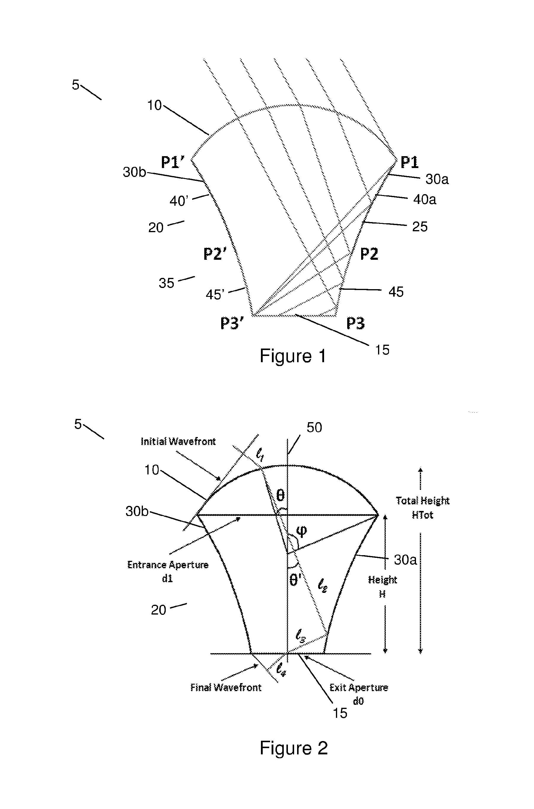
[0172]In a specific example, the trial front surface 10 arc angle φ is selected to be 30°, the dimension of the PV cell is chosen to be 1 cm×1 cm, the trial length of the entrance apertured1 is chosen to be 3 cm and the number of extreme rays N is selected to be 200. It will be appreciated that these represent arbitrary starting points for the iterative process and may be varied.

[0173]FIGS. 8(a) to (d), FIGS. 9(a) to (d) and FIGS. 10(a) to (d) show examples of optical elements 5 generated by the above process. The optical element 5 in each case is symmetrical in the x and z-axes. Each optical element 5 is presented from different angles; from a perspective view in FIGS. 8(a), 9(a) and 10(a); from the top, looking down through the front surface 10 in FIGS. 8(b), 9(b) and 10(b) and two different sides in FIGS. 8(c), 8(d), 9(c), 9(d), 10(c) and 10(d).

[0174]The optical element 5 shown in FIGS. 8(a) to (d) was generated by selecting the total height HTot to be 6.5 cm, the acceptance angl...


PUM


Abstract

An optical element and associated methods for generating an optical element and apparatus comprising the optical element, wherein the optical element comprises a first surface (10), a second surface (15), and a side wall structure (25) between the first and second surfaces. The side wall structure has an internally reflecting profile such that optical radiation incident on the first surface at an angle less than or equal to an acceptance angle and then incident on the side wall structure is internally reflected to the second surface by the side wall structure. In a first cross section of the optical element, the side wall structure has a first internally reflecting profile and / or the first surface has a first cross sectional profile. In a second cross section that is rotated relative to the first cross section, the side wall structure has a second internally reflecting profile and / or the first surface has a second cross sectional profile, wherein the second internally reflecting profile of the side wall structure and / or the second cross sectional profile of the first surface is different from the first internally reflecting profile of the side wall structure and / or the first cross sectional profile of the first surface.

Description

FIELD OF THE INVENTION[0001]The present invention relates to an optical element, such as a concentrator lens for a system using solar energy. The present invention also relates to associated methods of generating and producing an optical element and / or solar collection or energy apparatus comprising the optical element.BACKGROUND TO THE INVENTION[0002]Optical concentrator elements may be utilised in a variety of applications, but are particularly useful in systems that operate using solar radiation, such as solar power, heating and / or lighting systems.[0003]For example, in a photovoltaic system, the cost of the photovoltaic material generally contributes significantly to the overall cost of the system. Furthermore, although more modern photovoltaic materials such as GaAs may be more efficient than traditional amorphous silicon materials, the efficiency of photovoltaic materials is often low, typically being less than 20% and may be even less than 10% efficient. However, the most eff...

Claims


Application Information

Patent Timeline
Patent Type & Authority Applications(United States)
IPC IPC(8): G02B19/00G06F17/50H01L31/052F24S23/30
CPCG02B19/0028G06F17/50H01L31/0522H01L31/02325G02B19/0042Y02E10/52H01L31/0543H01L31/0547Y02E10/40Y02B10/20F24S23/30H01L31/054H01L31/0232
Inventor RAMIREZ-INIGUEZ, ROBERTOSUKKI, FIRDAUS MUHAMMADSTEWART, BRIANMCMEEKIN, SCOTT
Owner UNIV COURT OF GLASGOW CALEDONIAN UNIV
Why Eureka
Try Eureka