Method for calibrating camera measurement system
a camera and measurement system technology, applied in the field of calibration camera measurement system, can solve problems such as difficulties in view of a calibration method, and achieve the effect of simple calibration method and easy manufactur
- Summary
- Abstract
- Description
- Claims
- Application Information
AI Technical Summary
Benefits of technology
Problems solved by technology
Method used
Image
Examples
embodiment 1
[0094]1) The present invention is exclusively used to measure a shape of a hole, interior parameters in a camera (focus distance: (f×kx, f×ky), displacement of a main point: (cx, cy), distortion correction coefficient in a radial direction: (k1, k2, k3), distortion correction coefficient in a tangential direction: (p1, p2)) are specifically set as follows:[0095](1) Regarding a camera and a lens within the camera, a distortion in a tangential direction is little so that distortion correction coefficient in a tangential direction: (p1, p2) can be ignored and the all set to zero.[0096](2) A purpose of the measurement according to the present invention is to measure a shape of a hole wherein a measured shape of the hole is aligned at a central portion of an image. Therefore, an influence of the distortion in the radial direction is not occurred. Therefore, in the system according to the present invention, there is no problem even if the all distortion correction coefficients in the radi...
embodiment 2
[0106]1) The present invention is exclusively used to measure a shape of a hole, interior parameters in a camera (focus distance: (f×kx, f×ky), displacement of a main point: (cx, cy), distortion correction coefficient in a radial direction: (k1, k2, k3), distortion correction coefficient in a tangential direction: (p1, p2)) are specifically set as follows:[0107](1) Regarding a camera and a lens within the camera, a distortion in a tangential direction is little so that distortion correction coefficient in a tangential direction: (p1, p2) can be ignored and the all set to zero.[0108](2) A purpose of the measurement according to the present invention is to measure a shape of a hole wherein a measured shape of the hole is aligned at a central portion of an image. Therefore, an influence of the distortion in the radial direction is not occurred. Therefore, in the system according to the present invention, there is no problem even if the all distortion correction coefficients in the radi...
embodiment 3
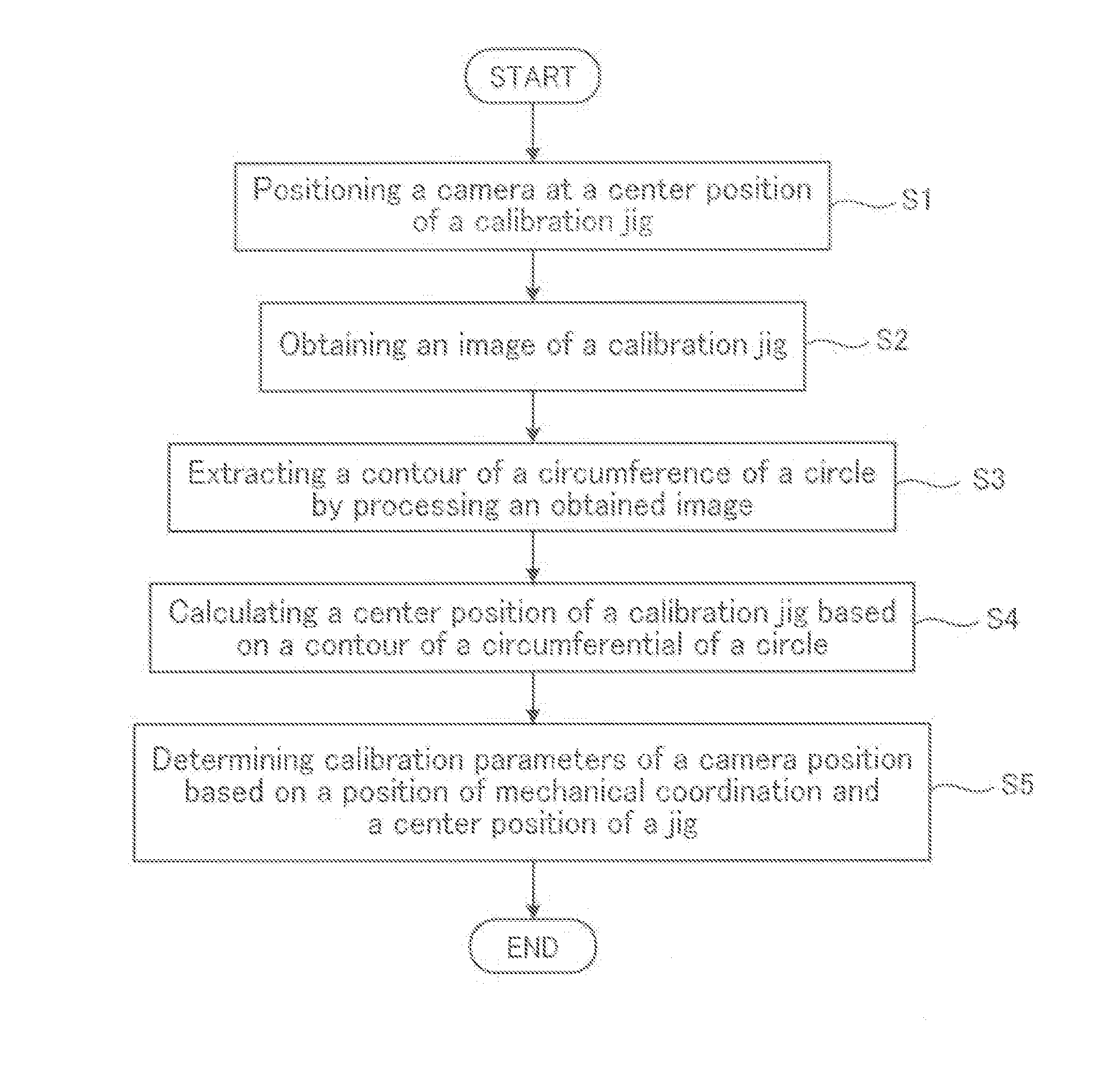
[0118]FIG. 16 shows the third embodiment of the present invention. FIG. 16 is a flow chart for showing a calibration method according to the present invention.
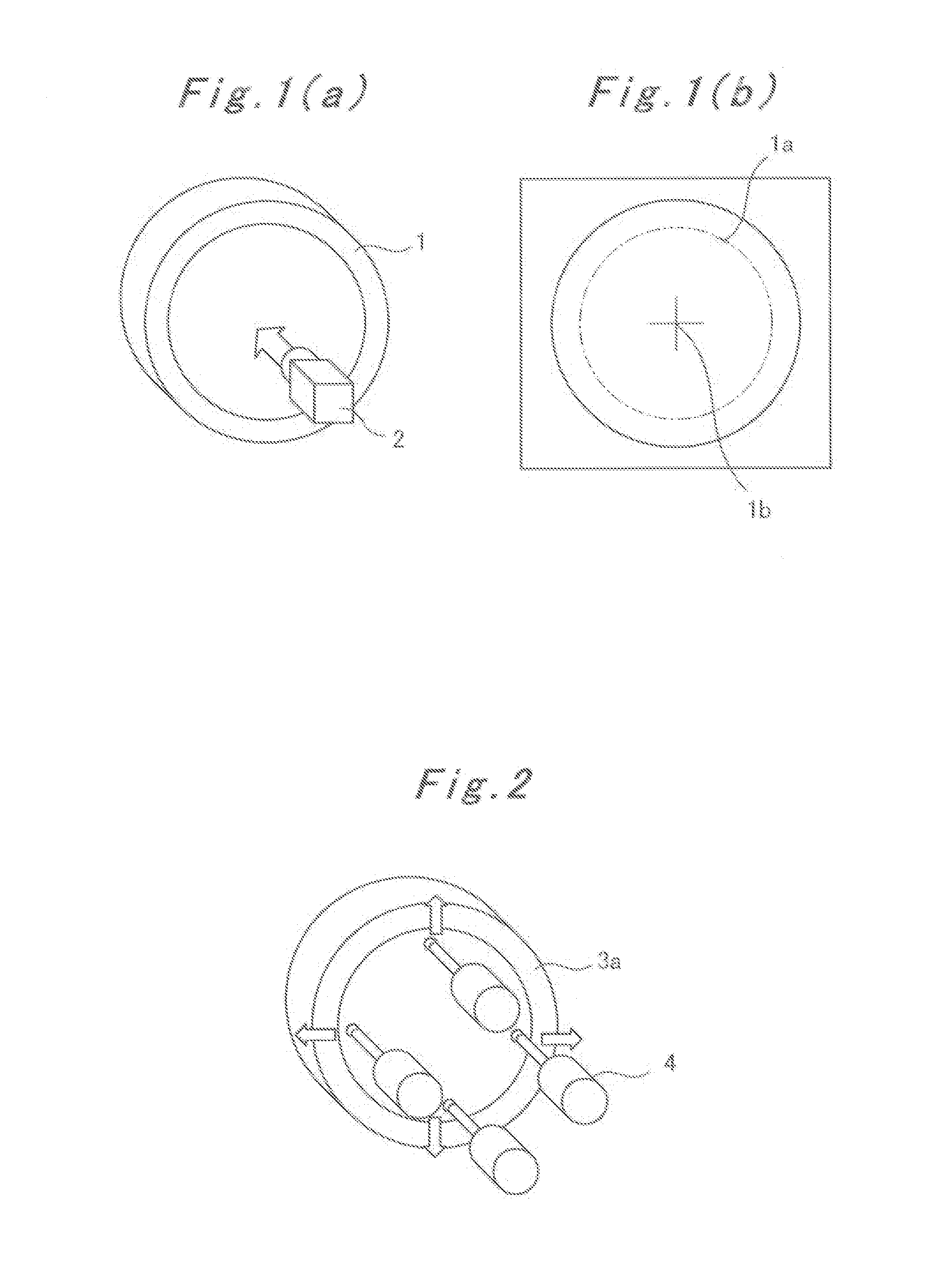
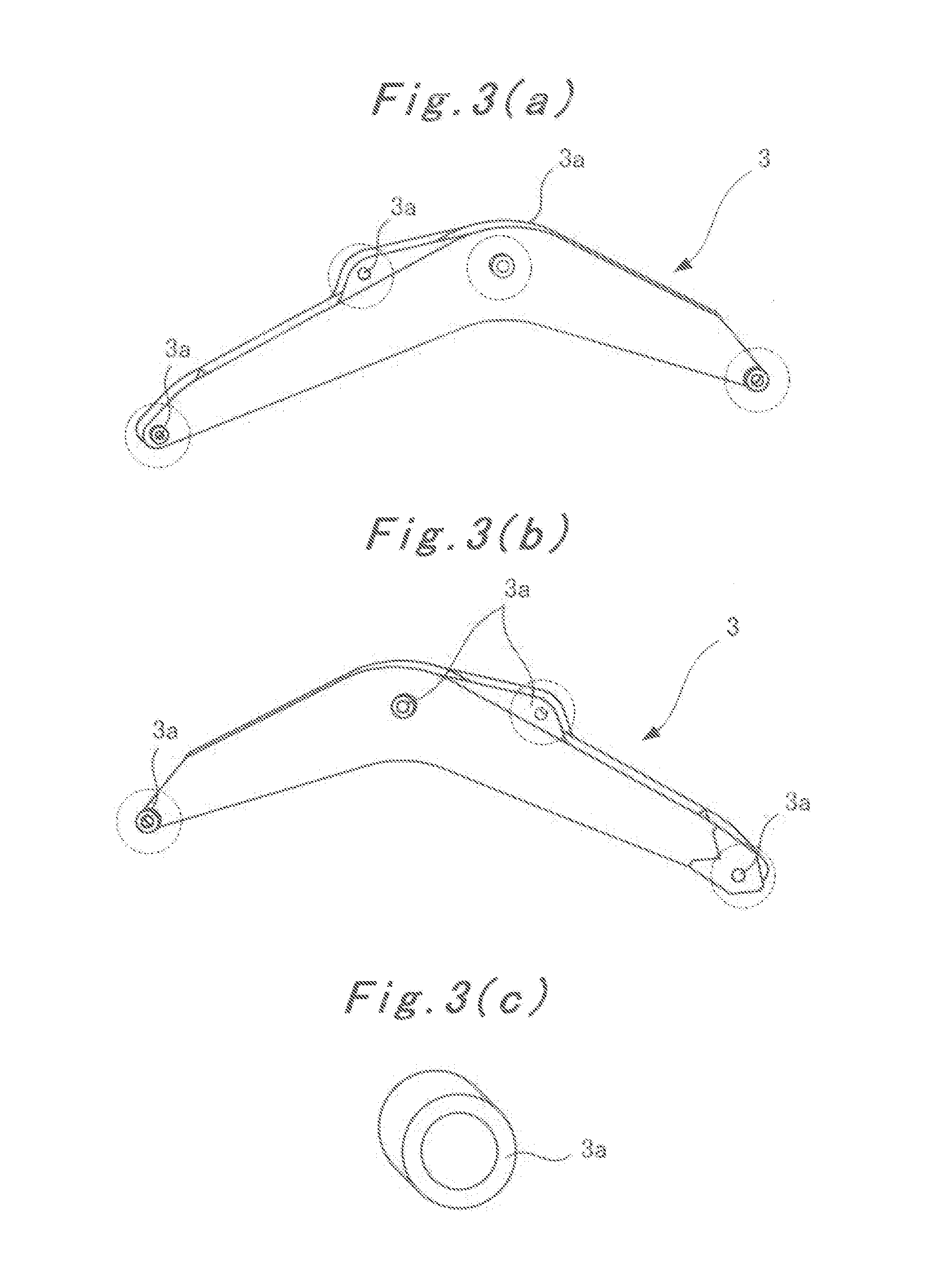
[0119]As shown in FIG. 1(a), a camera 2 is positioned near a center position of a calibration jig 1 (STEP S1). The calibration jig 1 is previously set on a workpiece on a machining tool, for instance a boom 3 of a hydro pressure shovel as shown in FIG. 3. As shown in FIG. 15, a relation between the coordination of the camera 2 and a machine coordination may be specifically related (Embodiment 1) or may be unrelated (Embodiment 2).
[0120]In the next, an image of the calibration jig 1 is photographed by a camera 2 (STEP S2).
[0121]Then, as shown in FIG. 1(b), a contour 1a of a circumferential of a circle setting a ring-shaped calibration jig at a workpiece on a machining tool is extracted by processing an image photographed by the camera (STEP S3).
[0122]Then, as shown in FIG. 1(b), a center position 1b of the calibration jig 1 is ...
PUM
 Abstract
Description
Claims
Application Information
 - R&D
- Intellectual Property
- Life Sciences
- Materials
- Tech Scout
- Unparalleled Data Quality
- Higher Quality Content
- 60% Fewer Hallucinations
Browse by: Latest US Patents, China's latest patents, Technical Efficacy Thesaurus, Application Domain, Technology Topic, Popular Technical Reports.
© 2025 PatSnap. All rights reserved.Legal|Privacy policy|Modern Slavery Act Transparency Statement|Sitemap|About US| Contact US: help@patsnap.com


