Dewatering Method for Correcting Water Content of Green Veneer for Plywood and Apparatus for Dewatering the Green Veneer

a green veneer and water content technology, applied in the direction of veneer presses, lamination ancillary operations, applications, etc., can solve the problems of large time consumption of the apparatus for dewatering the green veneer one by one, difficult to achieve the effect of equal drying of the green veneer, and high labor intensity

Active Publication Date: 2014-11-13
TAIHEI SEISAKUSHO AKA TAIHEI MACHINERY WORKS
View PDF3 Cites 3 Cited by
  • Summary
  • Abstract
  • Description
  • Claims
  • Application Information

AI Technical Summary

Benefits of technology

[0013]The invention provides a dewatering method as described below. A large number of green veneers for plywood respectively having high water contents and formed in a rectangular shape are vertically laminated to obtain a veneer laminate having a quadrangular prismatic shape. Cut faces of the green veneers for plywood, which are end faces of the green veneers for plywood intersecting with a direction of fibers, are vertically aligned. The veneer laminate is located between upper and lower platen members so that two opposite side faces of the veneer laminate vertically form cut face gathering planes. The upper and lower platen members are moved toward each other to apply a pressing force in the range of 15 to 50 kg / cm2 (or more preferably in the range of 20 to 40 kg / cm2) to the large number of laminated green veneers for plywood constituting the veneer laminate. Accordingly, water contained in the green veneers for plywood is drawn through the cut faces of the green veneers and drips downward along the cut face gathering planes vertically formed where the cut faces of the green veneers for plywood are gathered. The pressing force applied to the veneer laminate is released or weakened in the range of 0 to 10 kg / cm2 (or more preferably in the range of 0 to 5 kg / cm2) while the water is dripping downward so that the cut faces and fibers inside of the green veneers for plywood spread in a direction of original shape of the green veneers, generating a negative pressure. The water dripping downward along the cut face gathering planes is suctioned into fibers of the green veneer having a relatively low water content by a suctioning action generated from the cut faces toward the inside by the negative pressure. Then, the pressing force in the range of 15 to 50 kg / cm2 is applied again to the large number of green veneers for plywood. As a result of at least one cycle of these steps that ends with the application of pressing force, a variability of the water contents in the veneer laminate is lessened among the green veneers for plywood and in different parts of each of the green veneers for plywood while an overall water content of the veneer laminate is reduced.
[0035]According to the apparatus, the lifting cylinders having outputs relatively small but large enough to lift the pressing member are used to return the pressing member to the lift-up position, making it unnecessary to drive the pressing cylinders with very large outputs. This leads to energy saving. Further, in the apparatus, the stroke distances of the plurality of lifting cylinders is measured and the plurality of pressing cylinders is individually controlled so that the tilt of the pressing member is corrected based on the measured values. The apparatus can horizontally retain the veneer laminate as equally in height as possible during the pressing, thereby evenly dewatering the veneer laminate.

Problems solved by technology

In the process, the green veneers are compressed and dewatered by applying a pressure to the green veneers before the drying step because it is time-consuming to immediately dry the obtained green veneers.
A large difference between the water contents leads to a lengthy drying step and makes it difficult for the green veneers to be equally dried, in which case the water contents are still different from one green veneer to another and in different parts of one green veneer after the drying step.
When the green veneers thus having different water contents are laminated to produce the plywood, warp and / or distortion is likely to occur.
This apparatus which dewaters the green veneers one by one needs an extensive time for its whole operation.
Further, the apparatus, wherein all of the green veneers are uniformly pressed by the rollers, is unable to correct a variability of water contents among the different green veneers.
However, the apparatus is similarly unable to correct a variability of water contents, whether they are different water contents among the green veneers and / or different water contents in different parts of one green veneer.

Method used


Image

  • Dewatering Method for Correcting Water Content of Green Veneer for Plywood and Apparatus for Dewatering the Green Veneer
  • Dewatering Method for Correcting Water Content of Green Veneer for Plywood and Apparatus for Dewatering the Green Veneer
  • Dewatering Method for Correcting Water Content of Green Veneer for Plywood and Apparatus for Dewatering the Green Veneer

Examples


Embodiment Construction

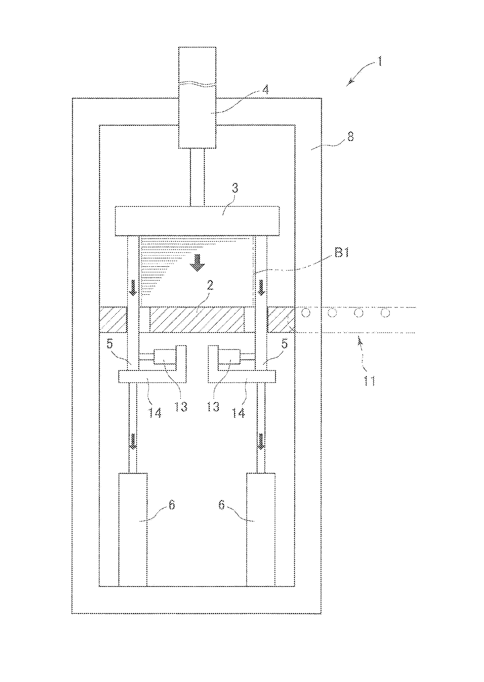
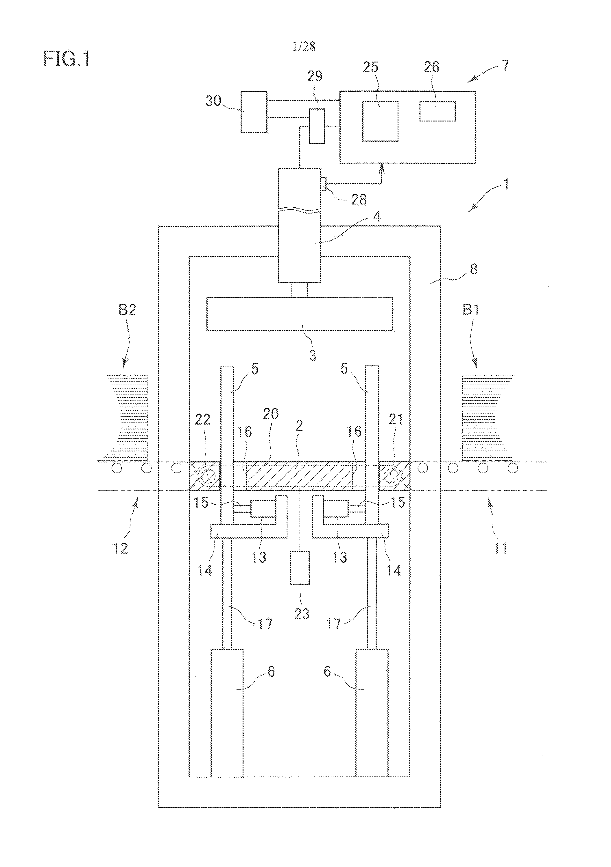
[0074]An exemplary embodiment of the invention is described referring to examples illustrated in the accompanied drawings. First, a dewatering apparatus for correcting water contents suitably used in a method according to the invention is described. Then, examples of the method according to the invention are described in a manner that corresponds to the description of operations of the apparatuses. FIG. 1 illustrates a green veneer dewatering apparatus 1 adapted to vertically apply a pressing force and thereby compress a veneer laminate (green veneer laminate) composed of a large number of vertically laminated green veneers for plywood to dewater the veneer laminate for reduction of a water content of the veneer laminate. The green veneer dewatering apparatus 1 has a support platen 2 supporting the veneer laminate, a press platen 3 provided in an upper section of the support platen 2 and serving as a pressing member movable toward and away from the support platen 2, a pressing cylin...


PUM

PropertyMeasurementUnit
water contentsaaaaaaaaaa
water contentaaaaaaaaaa

Abstract

A large number of green veneers for plywood respectively having high water contents and formed in a rectangular shape are vertically laminated to obtain a veneer laminate having a quadrangular prismatic shape. The veneer laminate is located between upper and lower platen members so that two opposite side faces of the veneer laminate vertically form cut face gathering planes. The upper and lower platen members are moved toward each other to apply a pressing force to the veneer laminate. The pressing force applied to the veneer laminate is released or weakened while the water drawn through the cut face gathering planes by the pressing force is dripping downward along the cut face gathering planes of the veneer laminate vertically formed.

Description

CROSS-REFERENCE TO RELATED APPLICATION[0001]This application is a divisional of copending U.S. utility application entitled, “Dewatering Method for Correcting Water Content of Green Veneer for Plywood and Apparatus for Dewatering the Green Veneer,” having Ser. No. 13 / 539,659, filed Jul. 2, 2012, which is entirely incorporated herein by reference.BACKGROUND OF THE INVENTION[0002]1. Field of the Invention[0003]The invention relates to a dewatering method for correcting water contents of green veneers for plywood. In the dewatering method, a pressure is vertically applied to a large number of vertically laminated green veneers for plywood so that the green veneers are compressed and dewatered for reduction of water contents of the green veneers. The invention also relates to an apparatus for dewatering the green veneers.[0004]2. Description of the Related Art[0005]Describing a plywood production process often employed, a log being rotated is peeled into thin band plates by the use of a...

Claims


Application Information

Patent Timeline
Patent Type & Authority Applications(United States)
IPC IPC(8): B30B9/04B32B38/00
CPCB30B9/047B32B38/164B32B38/0012B32B2038/166B32B2305/77B32B2309/12B32B2451/00B30B9/06B30B9/105B30B15/24B27D3/00F26B2210/14
Inventor NARITA, MITSUMASAOHDAIRA, YASUYUKI
Owner TAIHEI SEISAKUSHO AKA TAIHEI MACHINERY WORKS
Why Eureka
Try Eureka