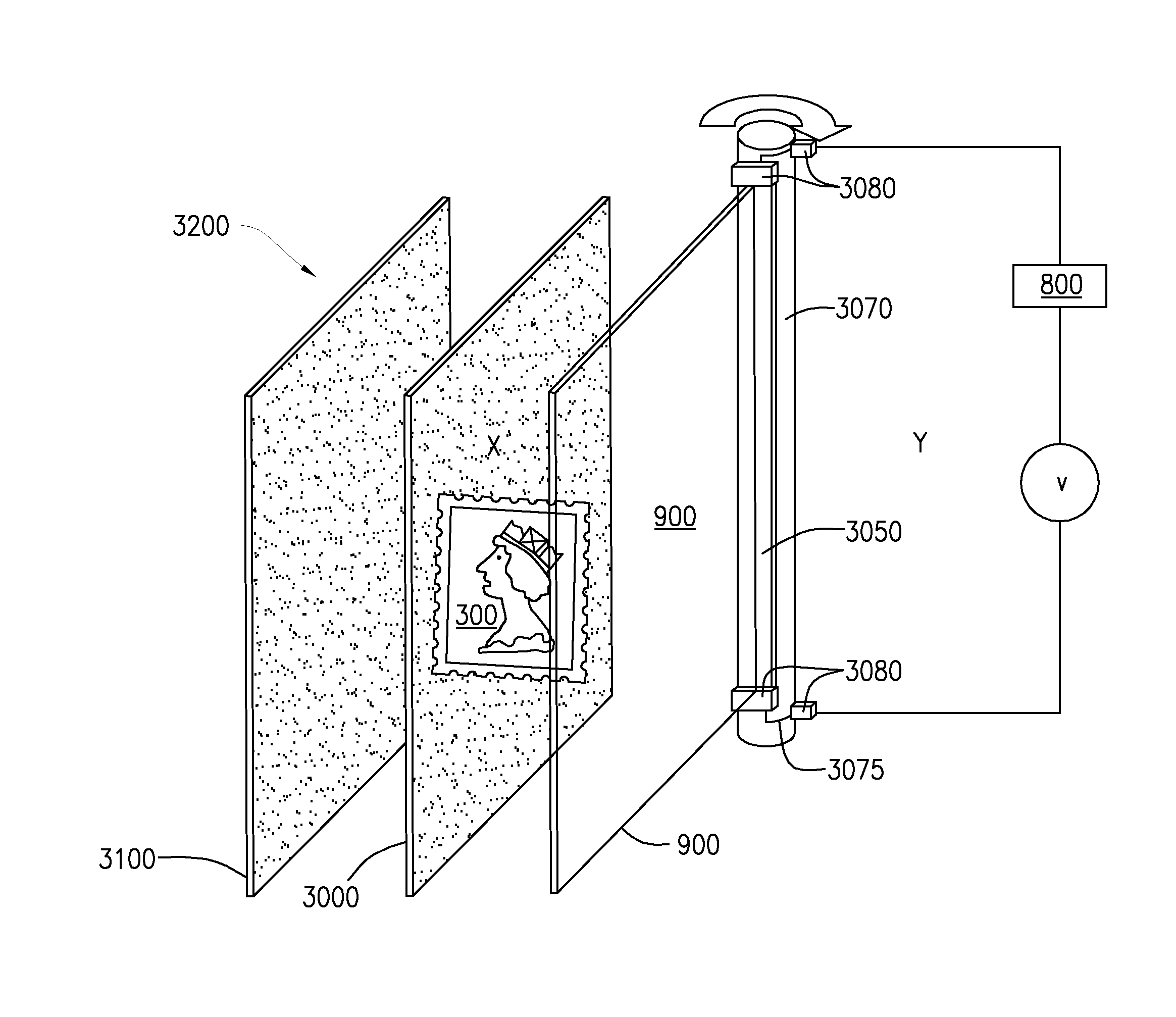
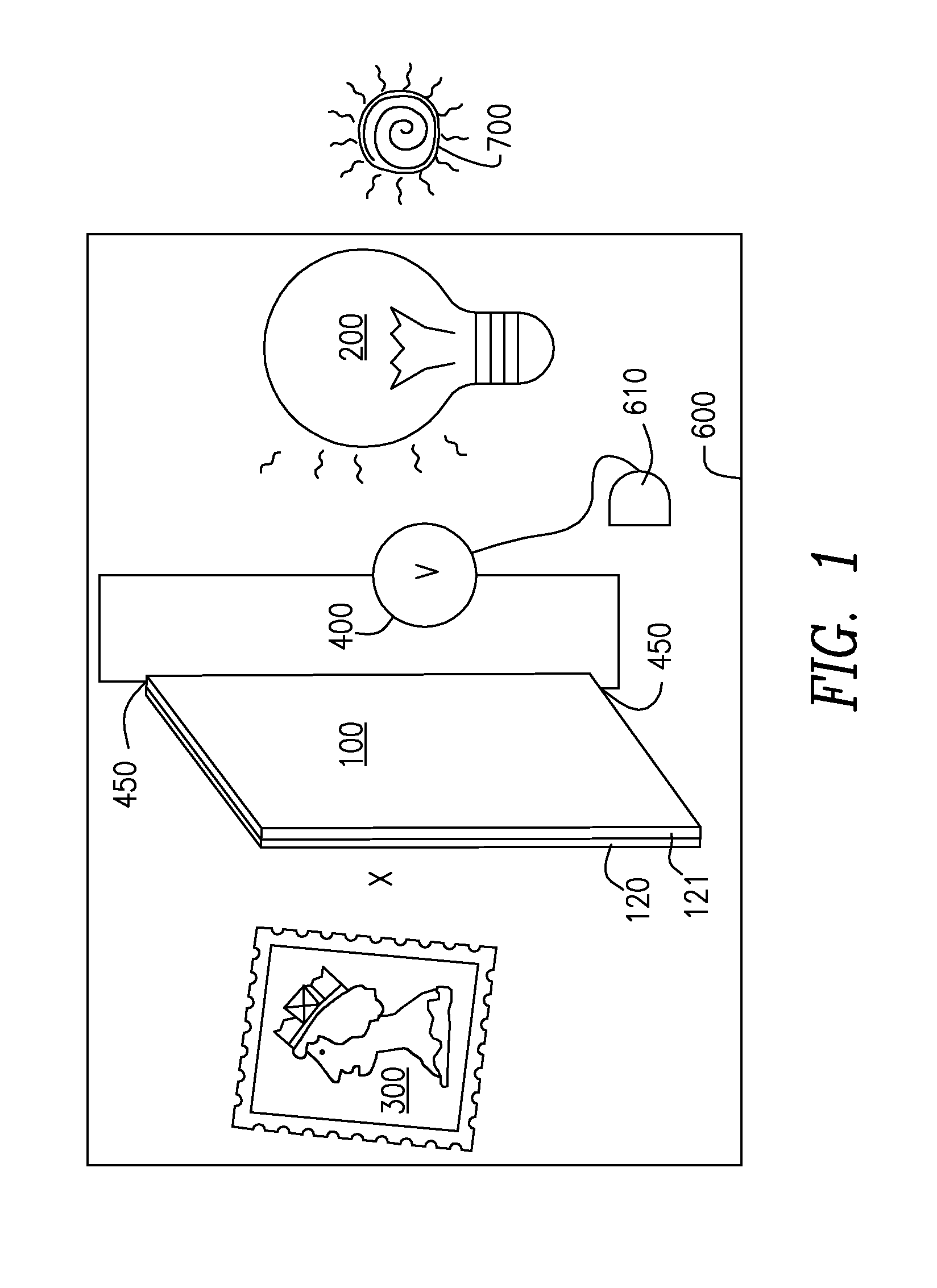
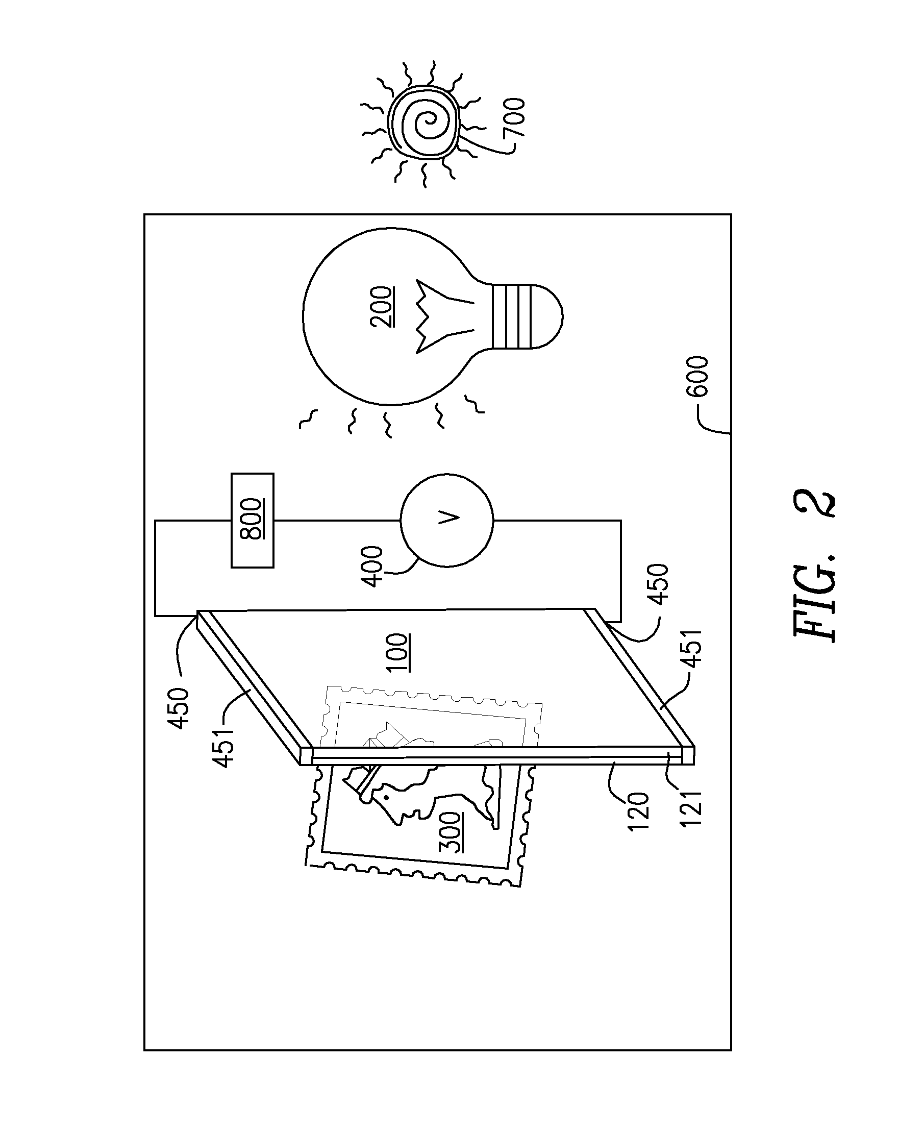
Method and device for protecting objects from degradation by light with suspended particle device light valves
a technology of suspended particles and light valves, which is applied in the field of preservation of objects illuminated with light, can solve the problems of affecting the quality and/or appearance of many types of articles, affecting the performance of the product, and affecting the quality of the product, so as to reduce the transmission of visible light, improve the functionality and performance of the product, and increase the maximum transmission level
- Summary
- Abstract
- Description
- Claims
- Application Information
AI Technical Summary
Benefits of technology
Problems solved by technology
Method used
Image

Examples
Embodiment Construction
[0059]Reference will now be made in detail to several embodiments of the invention that are illustrated in the accompanying drawings. Wherever practicable, the same or similar reference numerals are used in the drawings and the description to refer to the same or like parts or steps; however, to simplify the disclosure, the same or similar reference numerals may in some instances refer to parts or steps that comprise variants of one another. The drawings are in simplified form and not to precise scale. For purposes of convenience and clarity directional terms, such as top, bottom, left, right, up, down, over, above, below, beneath, rear, and front may be used with respect to the accompanying drawings. These and similar directional terms should not be construed to limit the scope of the invention in any manner. The terms “couple,”“connect” and similar terms with their inflectional morphemes are used interchangeably, unless the difference is noted or otherwise made clear from the cont...
PUM
| Property | Measurement | Unit |
|---|---|---|
| thickness | aaaaa | aaaaa |
| thickness | aaaaa | aaaaa |
| wavelength | aaaaa | aaaaa |
Abstract
Description
Claims
Application Information
 - R&D
- Intellectual Property
- Life Sciences
- Materials
- Tech Scout
- Unparalleled Data Quality
- Higher Quality Content
- 60% Fewer Hallucinations
Browse by: Latest US Patents, China's latest patents, Technical Efficacy Thesaurus, Application Domain, Technology Topic, Popular Technical Reports.
© 2025 PatSnap. All rights reserved.Legal|Privacy policy|Modern Slavery Act Transparency Statement|Sitemap|About US| Contact US: help@patsnap.com