
Heat pump cycle

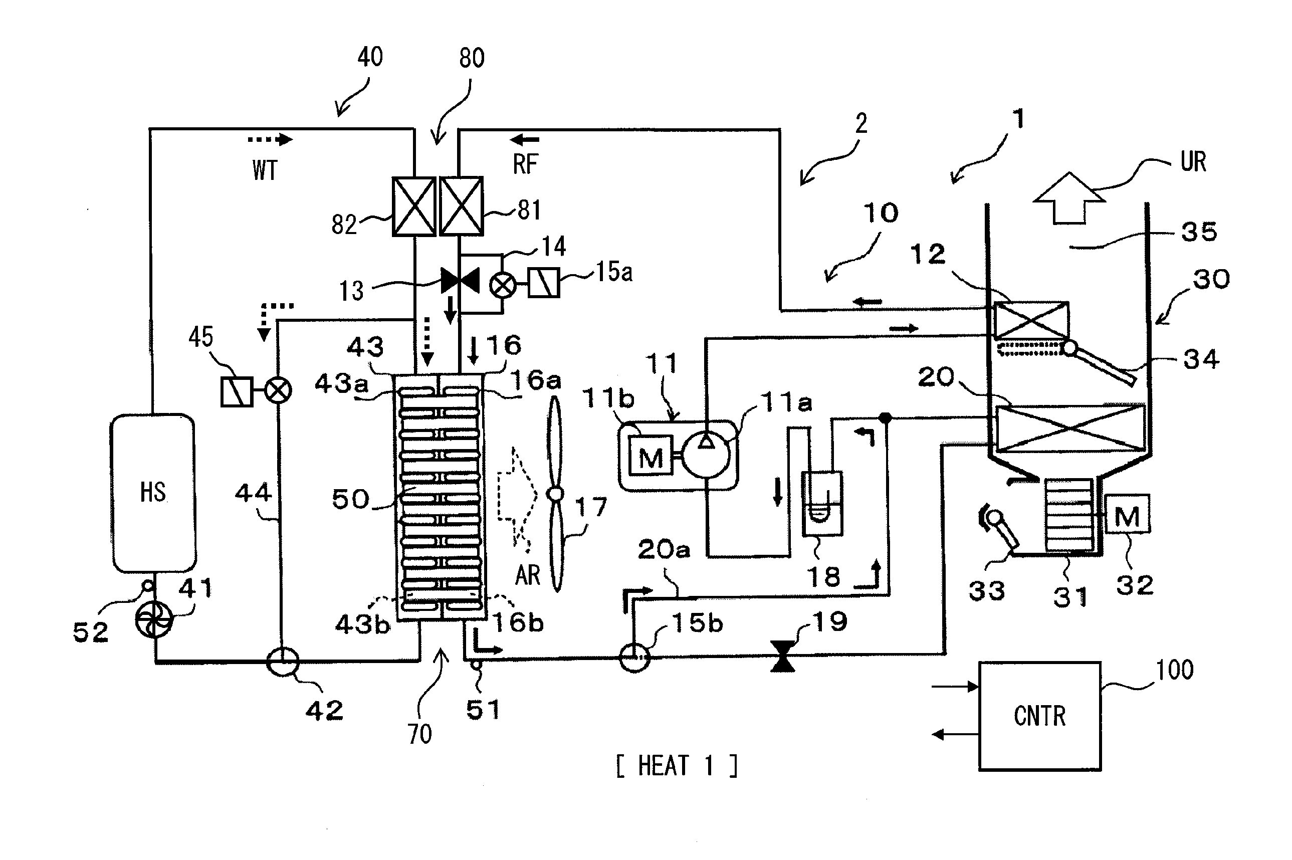
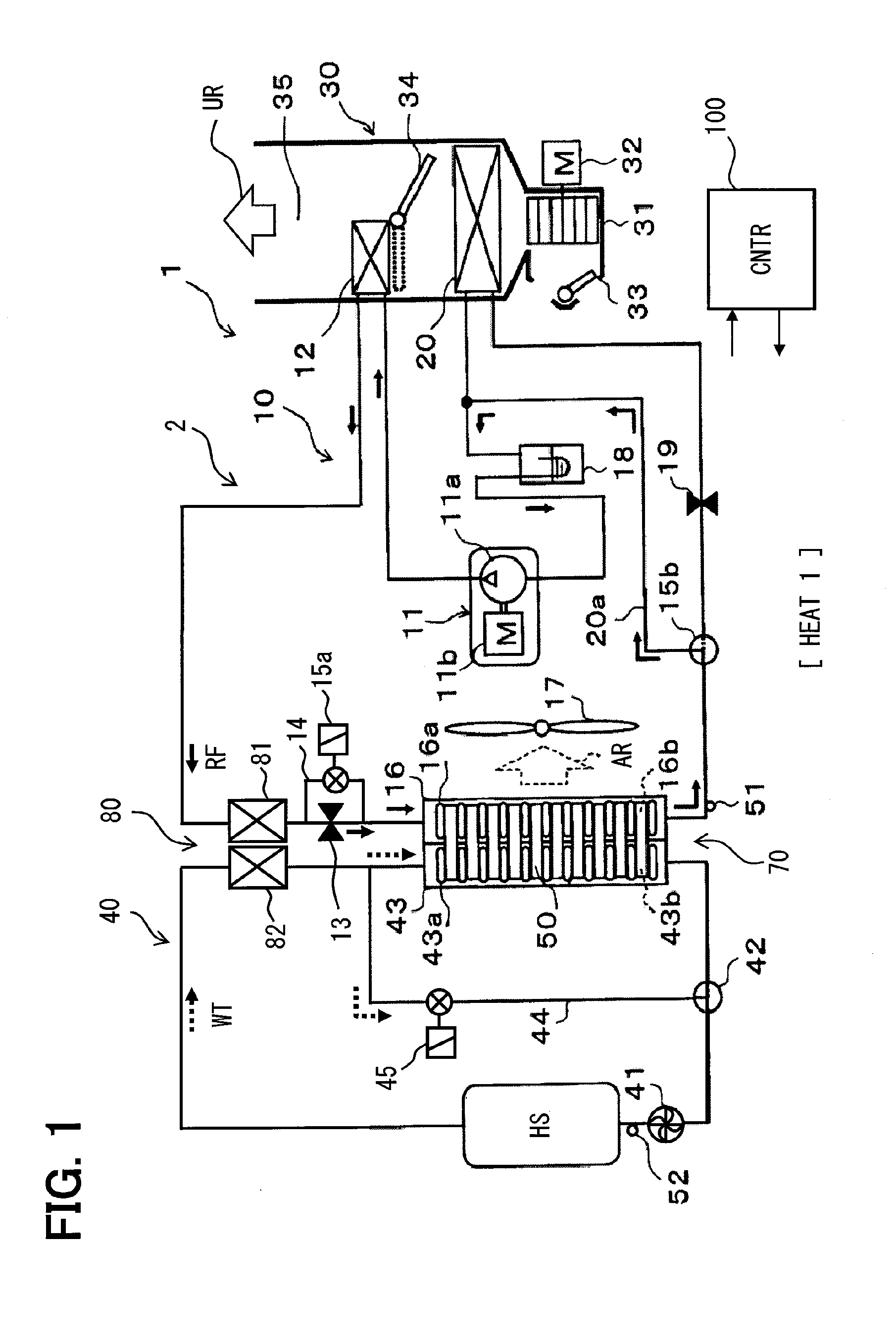
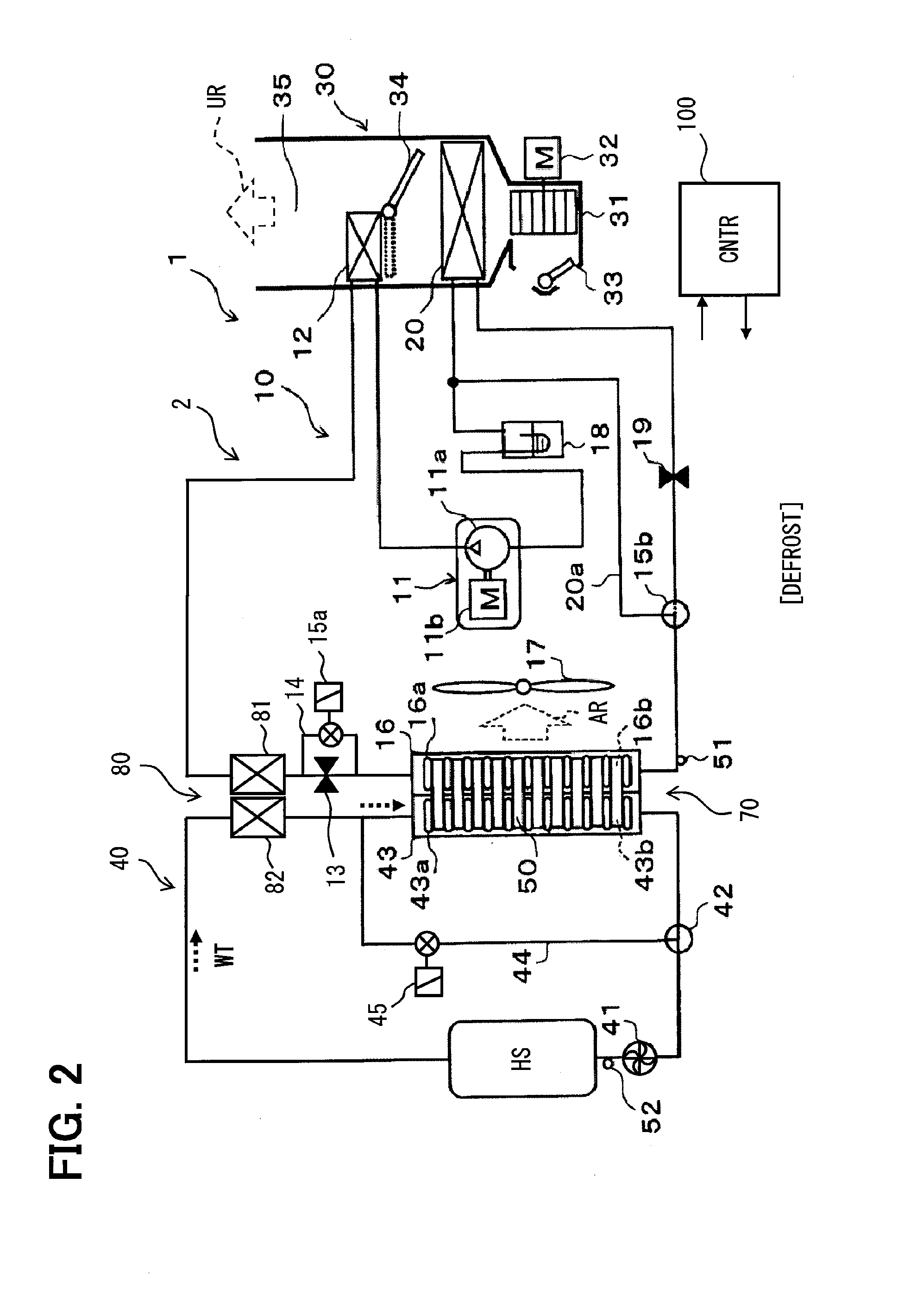
a heat pump and cycle technology, applied in heat pumps, lighting and heating apparatus, compression machines with several condensers, etc., can solve the problems of insufficient heat for defrosting, small waste heat of internal combustion engines, and small waste heat of electric devices such as electric motors, so as to reduce frost formation and/or improve defrosting performance.

Active Publication Date: 2014-10-30
DENSO CORP
View PDF4 Cites 48 Cited by
  • Summary
  • Abstract
  • Description
  • Claims
  • Application Information

AI Technical Summary

Benefits of technology

The present invention provides a heat pump cycle that improves suppression of frost formation and / or performance of defrosting without requiring an external heat source.

Problems solved by technology

However, in recent years, the waste heat of the internal combustion engine has a tendency to decrease.
For that reason, there is a risk that a sufficient amount of heat is not obtained for defrosting.
Also, in electric vehicles such as hybrid vehicles or electric automobiles, not only the waste heat of the internal combustion engine may be small, but also the waste heat from electric devices such as an electric motor may be also small.
For that reason, there is a risk that the sufficient amount of heat is not obtained for the defrosting.
Also, in view of another aspect, the technique of Patent Literature 1 may not pay sufficient attention to that the more necessity of the defrosting, the more suppression of adhesion and growth of frost before the adhesion of frost, in other words, Patent Literature 1 may not pay sufficient attention to the suppression of frost formation.
However, Patent Literatures 2 to 5 each disclose a structure of the heat exchanger, but may not conduct defrosting with the use of an appropriate heat source for defrosting.

Method used


Image

  • Heat pump cycle
  • Heat pump cycle
  • Heat pump cycle

Examples


tenth embodiment

[0194]In the above embodiment, the heat of refrigerant in the refrigerant circuit 10 is supplied indirectly to the heat exchanger 70 through the coolant WT. Instead, the heat of the high-pressure refrigerant in the refrigerant circuit 10 may be transferred directly to the exterior heat exchanger 16 that functions as the evaporator of the refrigerant circuit 10, and the heat exchanger 70 including the exterior heat exchanger 16. In this embodiment, as illustrated in FIG. 19, a radiator 43e of the heat exchanger 70 is used as the heat exchange portion 81 for extracting the heat from the high-pressure refrigerant. The high-pressure refrigerant is supplied to the radiator 43e. With this configuration, the constituent components of the heat exchanger 70 are heated directly by the high-pressure refrigerant. The refrigerant that has flowed out of the radiator 43e is introduced into the exterior heat exchanger 16 through the expansion valve 213. Hence, the radiator 43e may be used as an exa...

eleventh embodiment

[0198]In the above embodiment, the high-pressure refrigerant as the high-temperature medium HMD is introduced directly into the radiator 43e of the heat exchanger 70. Instead, in this embodiment, as illustrated in FIG. 21, the intermediate-pressure refrigerant is introduced directly into the radiator 43e of the heat exchanger 70. The refrigerant circuit 10 is branched between the interior condenser 12 and the expansion valve 213. A decompressor 23 to an intermediate pressure is disposed in the branched passage. The intermediate-pressure refrigerant is supplied to the radiator 43e. A decompressor 24 that decompresses the intermediate-pressure refrigerant to the low-pressure refrigerant is disposed downstream of the radiator 43e.

[0199]The temperature of the intermediate-pressure refrigerant is higher than the temperature of the low-pressure refrigerant decompressed by the expansion valve 213. Hence, the temperature of the intermediate-pressure refrigerant within the radiator 43e is h...

twelfth embodiment

[0200]In the above embodiment, the intermediate-pressure refrigerant that has passed through the radiator 43e is decompressed to a lower pressure. Instead, in this embodiment, as illustrated in FIG. 22, the intermediate-pressure refrigerant is sucked into the gas injection port of the compressor 411. According to this configuration, the intermediate-pressure refrigerant can be supplied to the radiator 43e without use of the decompressor 24.


PUM


Abstract

A heat pump cycle includes a refrigerant circuit and a coolant circuit. A first heat exchanger and a second heat exchanger are disposed between the refrigerant circuit and the coolant circuit. The first heat exchanger includes an exterior heat exchanger that functions as an evaporator in a heating operation, and a radiator for radiating heat of a coolant. The second heat exchanger transmits a heat of high-pressure refrigerant to the coolant in the heating operation. A temperature of refrigerant within the second heat exchanger is higher than a temperature of refrigerant within the first heat exchanger. The heat obtained from the second heat exchanger is supplied to the first heat exchanger through the coolant. Further, the heat obtained from the second heat exchanger is stored in the coolant. In defrosting operation, the coolant that has stored the heat therein is supplied to the first heat exchanger.

Description

CROSS REFERENCE TO RELATED APPLICATION[0001]This application is based on and incorporates herein by reference Japanese Patent Applications No. 2011-266140 filed on Dec. 5, 2011, and No. 2012-250453 filed on Nov. 14, 2012.TECHNICAL FIELD[0002]The present disclosure relates to a heat pump cycle.BACKGROUND ART[0003]Patent Literature 1 discloses a heat pump cycle and a defrosting control of an evaporator. Patent Literatures 2 to 5 disclose heat exchangers that allow multiple media to flow.[0004]In a technique of Patent Literature 1, the defrosting is executed with the use of a waste heat of an internal combustion engine. However, in recent years, the waste heat of the internal combustion engine has a tendency to decrease. For that reason, there is a risk that a sufficient amount of heat is not obtained for defrosting. Also, in electric vehicles such as hybrid vehicles or electric automobiles, not only the waste heat of the internal combustion engine may be small, but also the waste heat...

Claims


Application Information

Patent Timeline
Patent Type & Authority Applications(United States)
IPC IPC(8): F25B30/02F25B47/00F25B47/02F25B6/00
CPCF25B30/02F25B47/025F25B47/006F25B6/00F28F9/26F25B5/04F25B6/04F25B25/005F25B2339/047F25B2400/0409F25B2600/2501B60H1/00921B60H2001/00949F28F9/0278F28F27/02F28D1/0408F28D1/05391F28D7/0025F28D7/106F28D2021/008Y02B30/52F28F1/128F28F2215/02B60H2001/00961
Inventor KATOH, YOSHIKISAKAMOTO, KOTAKAMI, YUUICHI
Owner DENSO CORP
Learn More