
Solar-power enhancing module and sun tracking system thereof

Inactive Publication Date: 2014-10-23
WANG YUN MIN
View PDF3 Cites 5 Cited by
  • Summary
  • Abstract
  • Description
  • Claims
  • Application Information

AI Technical Summary

Benefits of technology

The present disclosure is about a solar-power enhancing module and a sun tracking system that aims to improve the efficiency of sunlight collection. By using a pair of first reflector faces and a pair of second reflector faces, the module can focus more light on the solar panel, saving installation costs and boosting the intensity of light incident on photovoltaic units. The design of the reflector faces increases the value of solar devices by reducing the cost of assembling the solar panel.

Problems solved by technology

When collecting solar energy, the efficiency of the solar modules is limited by production material, assembly structure and other technical limitations.
Some energy is lost due to the inability of solar panels to convert light from the entire range of frequencies of solar light into electricity.
Other energy lost results from material and structure of the solar module.
These solutions are effective but costs such as particular materials and assembly processes renders the solutions economically impractical.

Method used


Image

  • Solar-power enhancing module and sun tracking system thereof
  • Solar-power enhancing module and sun tracking system thereof
  • Solar-power enhancing module and sun tracking system thereof

Examples


first embodiment

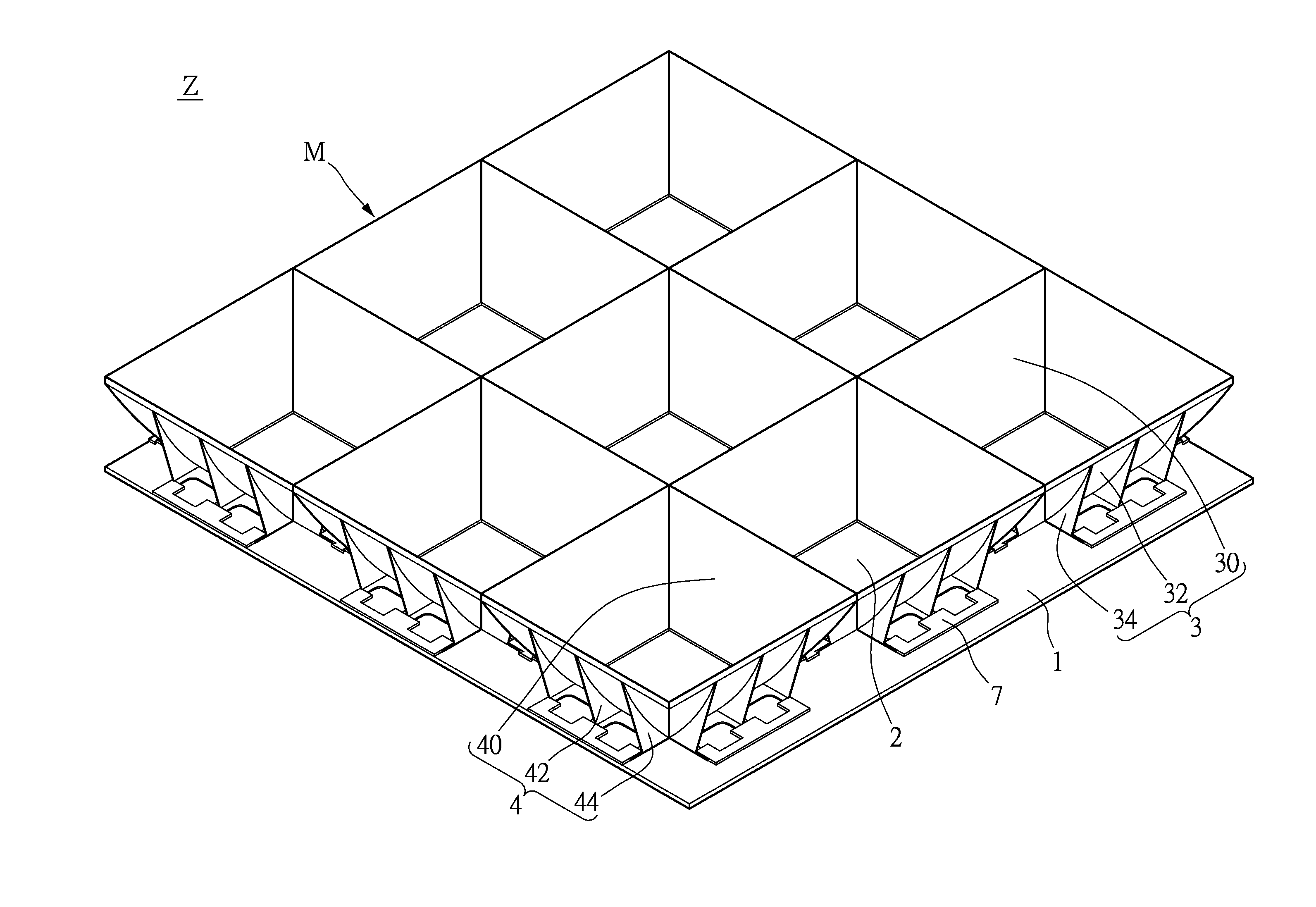
[0023]FIG. 1 shows a perspective view according to a first embodiment of the present disclosure. As seen in the figure, the present embodiment provides a solar-power enhancing module Z comprising: a base plate 1 and a plurality of photovoltaic units M. Each of the photovoltaic units M comprises: a solar panel 2, two first reflector boards 3 and two second reflector boards 4. The solar panel 2 is disposed on the base plate 1. The two first reflector boards 3 are disposed at two opposite sides of the solar panel 2 and on the base plate 1. Each of the first reflector boards 3 has a first reflector face 30 at the front (light receiving face) thereof. First support frames 34 support the first reflector boards 3. Additionally, two second reflector boards 4 are disposed at the other two sides of the panel 2 and on the base plate 1. Each of the second reflector boards 4 has a second reflector face 40. Each of the second reflector board 4 has a second support frame 44 supporting the backside...

second embodiment

[0040]FIG. 8 shows a schematic diagram of a sun tracking system 6 according to a second embodiment of the present disclosure. As shown in the above figure, the second embodiment of the present disclosure provides a sun tracking system 6 having a solar-power enhancing module Z, comprising: at least one solar-power enhancing module Z and a sun tracking system 6. The at least one solar-power enhancing device M comprises: a base plate 1 and a plurality of photovoltaic units M disposed on the base plate 1. Each of the photovoltaic units M comprises: a solar panel, two first reflector boards 3 and two second reflector boards 4. The sun tracking system 6 comprises: a support unit 60, a carrying unit 62 and at least one drive unit 64.

[0041]Refer to the first embodiment for the solar-power enhancing module Z, which is not further detailed herein. The main difference between the second embodiment and the first embodiment of the present disclosure lies in that: in the second embodiment, the su...


PUM


Abstract

The present disclosure provides a solar-power enhancing module comprising: a base plate and a plurality of photovoltaic units disposed on the base plate. Each of the photovoltaic units comprises: a solar panel, a pair of first reflector boards and a pair of second reflector boards. The two first reflector boards are disposed at two opposite sides of the photovoltaic unit. Each of the first reflector boards has a first reflector face at the front thereof. The two second reflector boards are disposed at the other two sides of the photovoltaic unit. Each of the second reflector boards has a second reflector face at the front thereof.

Description

BACKGROUND OF THE INVENTION[0001]1. Field of the Invention[0002]The present disclosure relates to a solar-power enhancing module; in particular, to a solar-power enhancing module having a solar base plate formed with a pair of first reflector boards and a pair of second reflector boards[0003]2. Description of Related Art[0004]When collecting solar energy, the efficiency of the solar modules is limited by production material, assembly structure and other technical limitations. Some energy is lost due to the inability of solar panels to convert light from the entire range of frequencies of solar light into electricity. Other energy lost results from material and structure of the solar module. The latter account for a larger portion of wasted energy.[0005]However, a typical solar power device disposes the solar panels outdoors, converts solar light into electrical energy in the form of direct current, uses an inverter to convert the direct current into an alternating current, and then ...

Claims


Application Information

Patent Timeline
IPC IPC(8): H01L31/052H01L31/042F24S50/20F24S23/70
CPCH01L31/0525H02S20/00H01L31/0422H01L31/0547H02S20/32Y02E10/52
Inventor WANG, YUN-MIN
Owner WANG YUN MIN
Learn More