
Large-view-field miniature imaging system

An imaging system and technology with a large field of view, applied in optical components, optics, instruments, etc., can solve the problems of difficult design, heavy volume and weight, and high processing cost, and achieve reduced design difficulty, compact lens structure, and reduced design. effect of difficulty

Active Publication Date: 2015-10-07
NANJING UNIV 5D TECH
View PDF5 Cites 7 Cited by
  • Summary
  • Abstract
  • Description
  • Claims
  • Application Information

AI Technical Summary

Problems solved by technology

[0002] Large field of view imaging lenses are widely used in monitoring, aerial photography, scientific research, military and other fields. Existing large field of view lenses usually have the following disadvantages: low resolution; complex lens structure, which makes the volume and weight heavy, The design is difficult; the processing cost is high, the illuminance of the edge image plane drops rapidly, and there are edge vignetting, etc.
[0003] In order to achieve higher angular resolution in the imaging system, it is necessary to increase the focal length of the lens, and the aberration of the optical lens increases linearly with the focal length; to achieve a higher image plane illuminance, a small F# (ratio of the focal length to the aperture diameter) and a large Aperture (the reciprocal of F#), while the aberration and volume quality of the optical lens increase with the caliber; the increase of the aberration means that the correction and balance of the aberration is more difficult, and the complex multi-piece lens structure has to be adopted To correct and balance aberrations, which will increase design difficulty, volume weight and processing costs, etc.

Method used


Image

  • Large-view-field miniature imaging system
  • Large-view-field miniature imaging system
  • Large-view-field miniature imaging system

Examples


Embodiment Construction

[0025] The present invention will be further described below in conjunction with the accompanying drawings and embodiments.

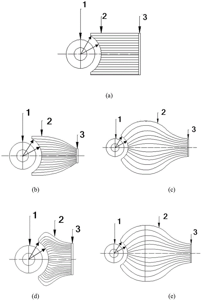
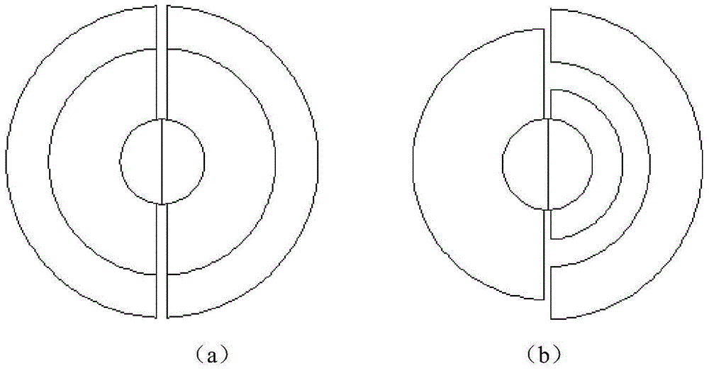
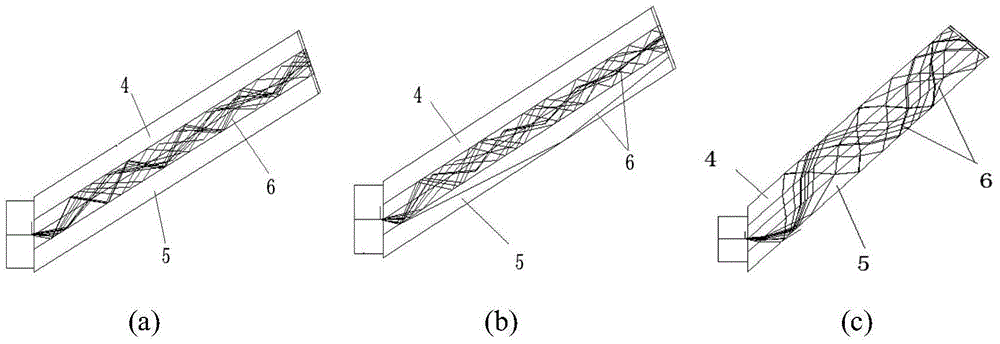
[0026] A novel imaging system with a large field of view in this embodiment includes three parts: a curved imaging lens 1 located at the front end, an optical fiber taper 2 and an imaging sensor 3 . The curved surface imaging lens 1 is composed of a plurality of spherical or hemispherical lenses or a combination of spherical and hemispherical lenses, each lens shares a spherical center, and its image surface is spherical. A diaphragm can be set at the center of the sphere, or stray light can be eliminated by setting a reasonable fiber taper numerical aperture and zoom ratio to realize the selection of the imaging beam. At this time, the fiber taper 2 acts as the aperture stop. The fiber cone 2 is spindle-shaped: wide in the middle and narrow at both ends. One end of the optical fiber taper 2 is a curved image surface, which is a spherical surface, whic...


PUM

PropertyMeasurementUnit
Heightaaaaaaaaaa

Abstract

The invention provides a large-view-field miniature imaging system, and belongs to the technical field of optical imaging. The imaging system comprises a curved surface imaging camera lens, an optical fiber taper and an imaging sensor. The curved surface imaging camera lens is formed by combining a plurality of spherical lenses or a plurality of semispherical lenses or is formed by combining the spherical lenses and the semispherical lenses. All the lenses share one sphere center. The image surface of the curved surface imaging camera lens is a spherical surface. One end of the optical fiber taper is a curved surface image surface, namely, a concave spherical surface coinciding with the image surface of the curved surface imaging camera lens. The other end of the optical fiber taper is a plane image surface, namely, a plane directly connected with the imaging sensor. The surface of the concave spherical surface is of a rough structure or a stair-shaped circular ring structure, and at the concave spherical surface end of the optical fiber taper, the included angle between each optical fiber forming the optical fiber taper and the image surface of the curved surface imaging camera lens ranges from 70 degrees to 90 degrees. The large-view-field miniature imaging system has the advantages of being large in view field, high in resolution, high in illumination, small in size, low in machining cost, and the like.

Description

technical field [0001] The invention belongs to the field of optical imaging, and in particular relates to a miniaturized imaging system with a large field of view. Background technique [0002] Large field of view imaging lenses are widely used in monitoring, aerial photography, scientific research, military and other fields. Existing large field of view lenses usually have the following disadvantages: low resolution; complex lens structure, which makes the volume and weight heavy, The design is difficult; the processing cost is high, the illuminance of the edge image plane drops rapidly, and there are edge vignetting, etc. [0003] In order to achieve higher angular resolution in the imaging system, it is necessary to increase the focal length of the lens, and the aberration of the optical lens increases linearly with the focal length; to achieve a higher image plane illuminance, a small F# (ratio of the focal length to the aperture diameter) and a large Aperture (the rec...

Claims


Application Information

Patent Timeline
IPC IPC(8): G02B13/06
Inventor 赵菲菲李想闫锋曹汛彭浩李正吉
Owner NANJING UNIV 5D TECH
Learn More