Exhaust gas heating method

a technology of exhaust gas and heating method, which is applied in the direction of mechanical equipment, machines/engines, electric control, etc., can solve the problems of incomplete combustion of ignited fuel, achieve the effect of suppressing the generation of smoke, reducing the oxygen concentration of exhaust gas, and increasing the combustion ra

Inactive Publication Date: 2014-10-23
TOYOTA JIDOSHA KK
View PDF1 Cites 3 Cited by
  • Summary
  • Abstract
  • Description
  • Claims
  • Application Information

AI Technical Summary

Benefits of technology

[0014]The flow rate of the exhaust gas flowing through the exhaust passage largely varies depending upon the operating state of the internal combustion engine. Thus, it is extremely difficult to perform accurate control on the combustion of the fuel supplied into the exhaust passage from the fuel supply valve without being affected by such variations in the flow rate of the exhaust gas. However, the present invention controls the air-fuel ratio of the exhaust gas which is released into the exhaust passage from the combustion chamber of the internal combustion engine when the fuel is supplied into the exhaust passage. Thus, the air-fuel ratio can fall within an area where the amounts of smoke and HC to be generated are both low. For example, when the exhaust gas heating device heats the exhaust gas in a state where the fuel injection into the combustion chamber of the internal combustion engine is stopped, such as during deceleration of the vehicle, fuel is supplied into the combustion chamber of the internal combustion engine without combustion and is mixed with the exhaust gas. This lowers the oxygen concentration of the exhaust gas, thereby making it possible to suppress the generation of smoke.
[0015]When the controlling step includes at least one of the steps of setting the fuel injection amount, setting the throttle valve opening degree, and setting the EGR control valve opening degree, the air-fuel ratio of the exhaust gas to be released into the exhaust passage from the combustion chamber of the internal combustion engine can be controlled rapidly and accurately.
[0016]When the fuel supply amount set in the step of setting the fuel supply amount is corrected by reducing it in accordance with the fuel injection amount set in the step of setting the fuel injection amount, the release of unburned fuel can further be suppressed.
[0017]Similarly, the release of unburned fuel can further be suppressed as well when the fuel injection amount set in the step of setting the fuel injection amount is corrected according to the exhaust gas temperature obtained in the step of obtaining the exhaust gas temperature. Specifically, the fuel injection amount is corrected by increasing it during an operating state in which the exhaust gas temperature is high, while the fuel injection amount set in the step of setting the fuel injection amount is corrected by reducing it during an operating state in which the exhaust gas temperature is low. In this way, the generation of smoke can be suppressed together with the suppression of unburned fuel.
[0018]When the exhaust gas heating method further includes the step of correcting the fuel injection amount set in the step of setting the fuel injection amount in accordance with the air-fuel ratio of the exhaust gas obtained in the step of obtaining the air-fuel ratio of the exhaust gas, an increase in the amount of unburned fuel can further be suppressed. Specifically, the fuel injection amount is corrected by increasing it in a case where the air-fuel ratio of the exhaust gas is within a lean region, while the fuel injection amount is corrected by reducing it in a case where the air-fuel ratio of the exhaust gas is within a rich region. In this way, the generation of smoke can be suppressed together with the suppression of unburned fuel.
[0019]When the exhaust gas purifying device includes a DPF, and the set fuel supply amount is corrected by reducing it in a case where fuel is supplied into the exhaust passage during a regeneration process of the DPF, the fuel consumption can be suppressed. Moreover, since the DPF is in the regeneration process, smoke generated can be removed through oxidation thereof. Furthermore, the burnability of PM (Particulate Matter) can be enhanced along with an increase in the oxygen concentration of the exhaust gas flowing into the DPF.

Problems solved by technology

Hence, the fuel supplied into the exhaust passage from the fuel supply valve and the exhaust gas may fail to be mixed sufficiently, leading to incomplete combustion of the ignited fuel in some cases.

Method used


Image

  • Exhaust gas heating method
  • Exhaust gas heating method
  • Exhaust gas heating method

Examples


Embodiment Construction

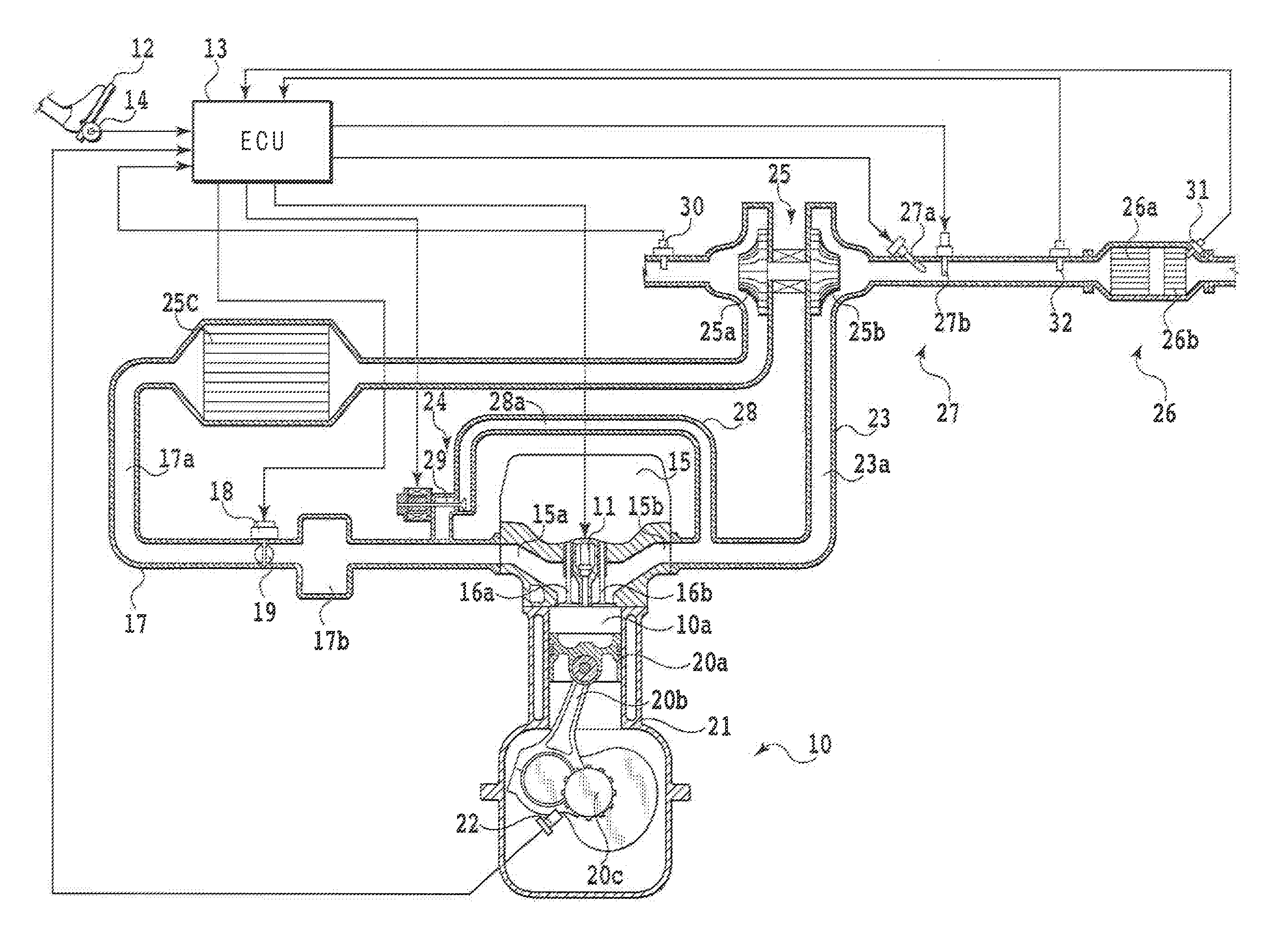
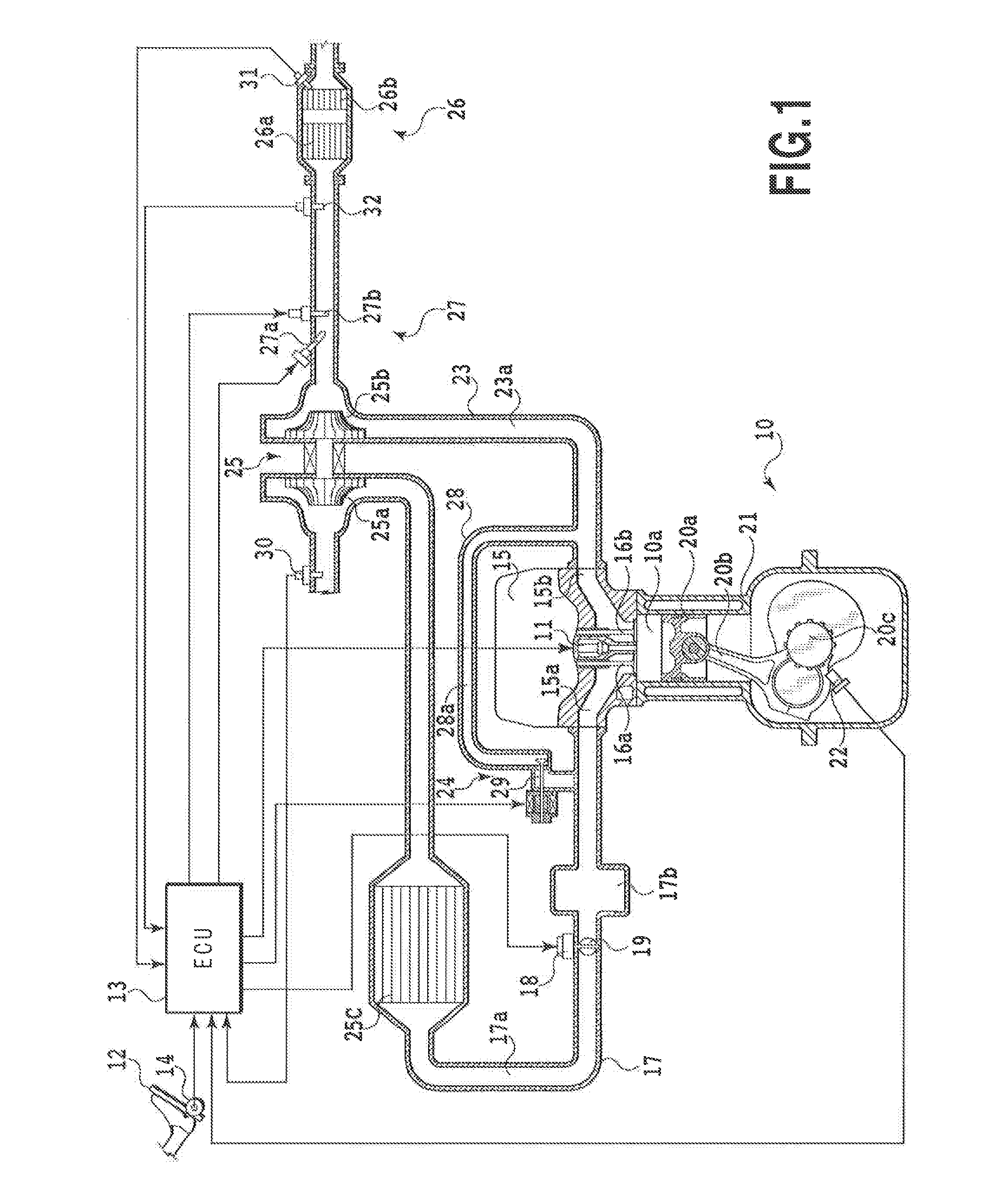
[0031]An embodiment of a compression-ignition internal combustion engine capable of implementing an exhaust gas heating method of the present invention will be described in detail with reference to FIGS. 1 to 11. Note that the present invention is not limited to this embodiment, and its configuration can be changed freely according to the specifications, characteristics, and the like required.

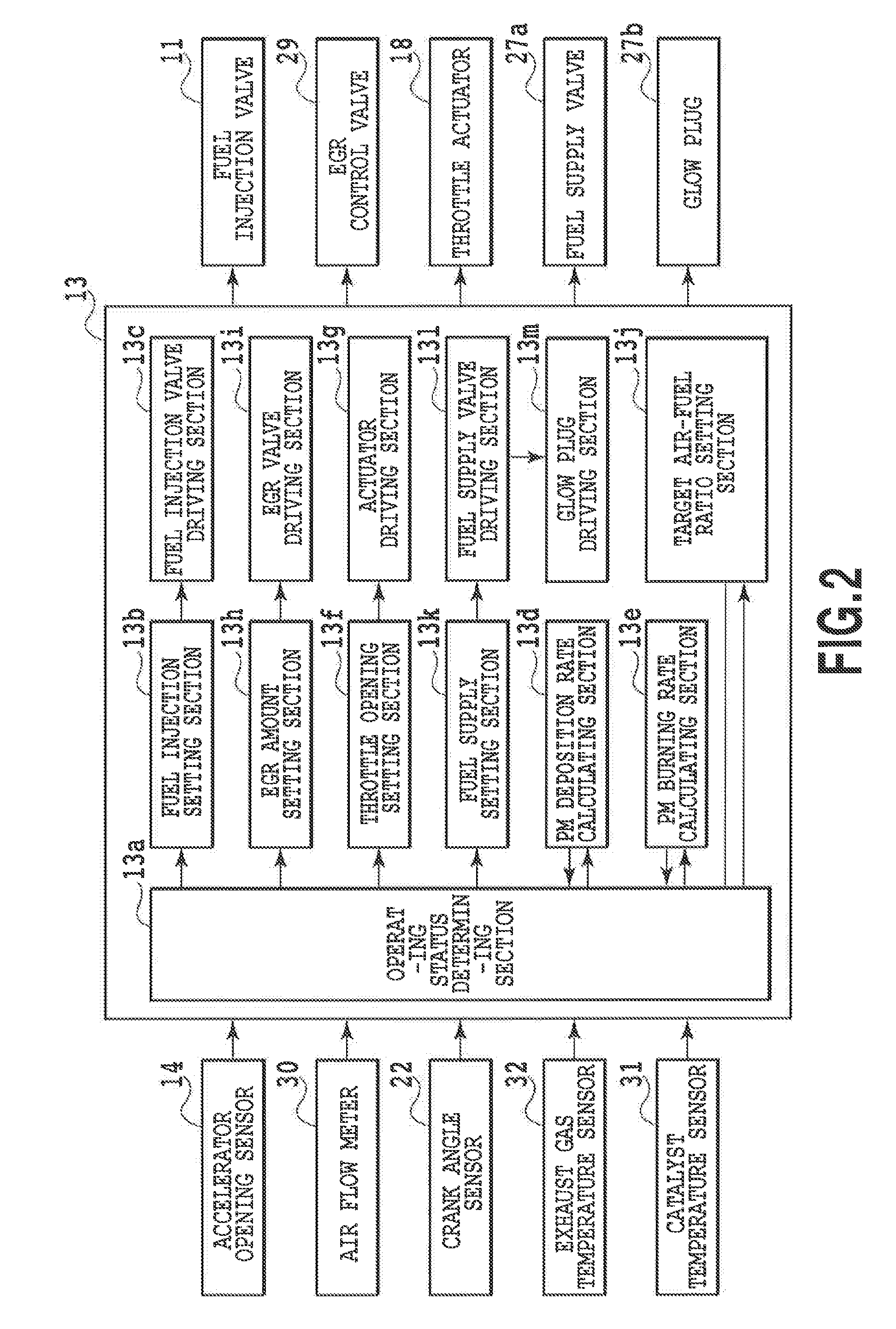
[0032]FIG. 1 schematically shows a main part of an engine system of this embodiment, and FIG. 2 shows a control block thereof. It is to be noted that a valve gear and the like for air intake and exhaust to and from an engine 10 are omitted in FIG. 1 for simplicity and convenience.

[0033]The engine 10 of this embodiment is an internal combustion engine of a compression ignition type which causes spontaneous ignition of diesel oil, serving as fuel, by injecting the diesel oil from a fuel injection valve 11 directly into a combustion chamber 10a being in a compressed state.

[0034]An ECU (Electronic ...


PUM


Abstract

A method according to the present invention of heating exhaust gas to be introduced into an exhaust gas purifying device from an internal combustion engine by heating and igniting fuel supplied into an exhaust passage from a fuel supply valve includes the steps of determining a necessity for supplying fuel into the exhaust passage, setting an amount of fuel to be supplied into the exhaust passage from the fuel supply valve, the amount being set when it is judged in the determining step that fuel needs to be supplied into the exhaust passage, checking an operating state of the engine, and controlling an air-fuel ratio of exhaust gas such that the air-fuel ratio falls within an area where amounts of both smoke and HC to be generated in the exhaust gas are low in the operating state of the engine checked in the checking step.

Description

CROSS-REFERENCE TO RELATED APPLICATIONS[0001]This application is a national phase application of International Application No. PCT / JP2012 / 000006, filed Jan. 4, 2012, the content of which is incorporated herein by reference.TECHNICAL FIELD[0002]The present invention relates to a method of heating exhaust gas to be introduced into an exhaust gas purifying device by supplying fuel into an exhaust passage from a fuel supply valve disposed upstream of the exhaust gas purifying device in an exhaust pipe, and then by heating and igniting the fuel.BACKGROUND ART[0003]In recent years, coping with strict emission standards set on internal combustion engines has lead to a necessity for facilitating the activation of an exhaust gas purifying device at the start of its internal combustion engine, maintaining its active state during the operation of the internal combustion engine, and so on. In this respect, Japanese Patent Laid-Open No. 2010-084710 and the like have proposed internal combustion ...

Claims


Application Information

Patent Timeline
Patent Type & Authority Applications(United States)
IPC IPC(8): F01N3/20
CPCF01N3/208F01N9/002F02B37/00F01N3/0231F01N3/0256F01N3/035F01N2900/0408F01N2900/08F01N2900/1402F01N2900/1404F02D41/029F02D2250/38F01N13/0097F01N3/0253F01N2240/14F01N2430/06F01N2610/03Y02T10/40
Inventor TSUJIMOTO, KENICHIINOUE, MIKIO
Owner TOYOTA JIDOSHA KK
Why Eureka
Try Eureka