Combustion control system of a diesel engine

a combustion control and diesel engine technology, applied in the direction of electrical control, process and machine control, instruments, etc., can solve the problems of nox, torque shock, difficult to perform proper fuel injection, etc., and achieve the effect of suppressing the generation of smoke and suppressing the discharge of nox

Inactive Publication Date: 2009-05-07
MITSUBISHI FUSO TRUCK AND BUS CORPORATION
View PDF18 Cites 6 Cited by
  • Summary
  • Abstract
  • Description
  • Claims
  • Application Information

AI Technical Summary

Benefits of technology

[0009]The present invention has been made to solve the foregoing problems. It is an object of the invention to provide a combustion control system of a diesel engine, which suppresses the generation of smoke and a torque shock by performing proper fuel injection at the time of a switching transition between a premix combustion mode and a normal combustion mode to enable a smooth transition, and is capable of suppressing NOx from being discharged even if an exhaust purification catalyst is in an inactive state.
[0011]Since the fuel-injection timing is controlled by switching between the normal combustion mode and the transition mode from one to the other according to the intake oxygen density, for example, even if an EGR system of a diesel engine delays in responding to a change of an engine operational state, it is possible to set a proper fuel-injection timing appropriate to an intake state, and then to suppress the generation of smoke.

Problems solved by technology

If this combustion control is employed, proper fuel injection is difficult to be performed, for example, in an engine having an EGR system due to a delay in operation of the EGR system during a time period of the switching transition between the combustion modes (during a transition mode).
This might cause smoke and a torque shock, and also might produce NOx.

Method used


Image

  • Combustion control system of a diesel engine
  • Combustion control system of a diesel engine
  • Combustion control system of a diesel engine

Examples


first embodiment

[0028]Firstly, a first embodiment will be described.

[0029]In an exhaust path of a diesel engine (hereinafter, referred to as engine) having a combustion control system according to the first embodiment of the invention, there is interposed a NOx catalyst (exhaust purification catalyst) that traps NOx (nitrogen oxides) contained in exhaust gas to reduce the NOx into harmless substances. The engine is provided with an EGR system and a common rail system. The EGR system includes an EGR path that connects the exhaust path and an intake path to each other. The EGR system has a function of suppressing the generation of NOx by opening / closing an EGR valve interposed in the EGR path to return a portion of the exhaust gas into intake air, thereby reducing combustion temperature.

[0030]The common rail system stores in a common rail the fuel that is highly pressurized with a fuel pump. The common rail system supplies the high-pressure fuel from the common rail to injectors of cylinders, and inj...

second embodiment

[0050]A second embodiment will be described below.

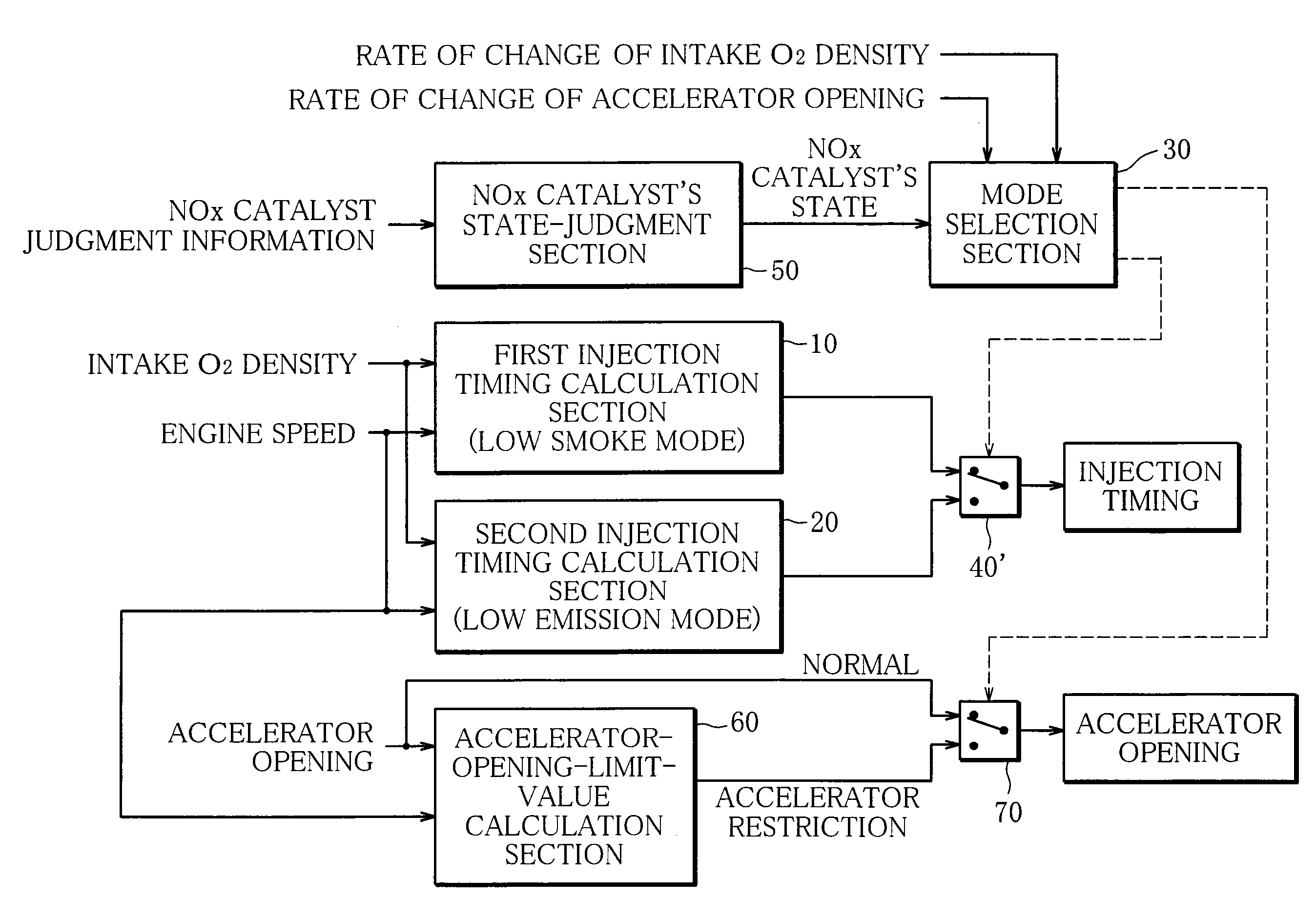
[0051]Unlike the first embodiment, in a combustion control system according to the second embodiment of the invention, the low emission mode and the low smoke mode are switched from one to the other according to whether the NOx catalyst is in the inactive state, and the accelerator opening is restricted so that the low emission mode is selected when the NOx catalyst is in the inactive state. The following description of the second embodiment will focus on the differences from the first embodiment.

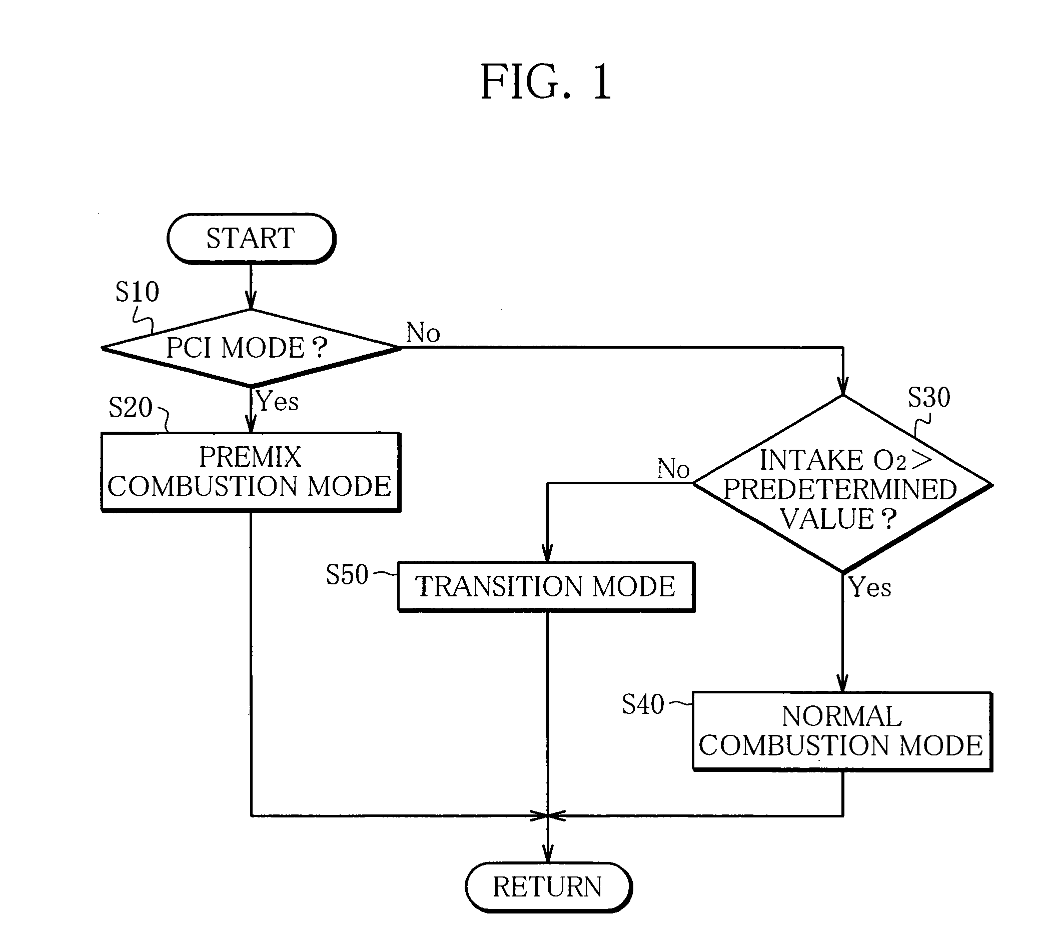
[0052]FIG. 10 is a flowchart showing the procedure of determining the switching between combustion modes according to the second embodiment of the invention. Steps S10 to S40 of the flowchart are the same as those in the first embodiment, so that the description thereof will be omitted.

[0053]Step S50′ makes a determination as to whether the NOx catalyst is in an active state. If the NOx catalyst is in the active state, the routine moves to S...


PUM


Abstract

A combustion control system of a diesel engine, which controls a fuel-injection timing by switching from one to another of a normal combustion mode, a premix combustion mode, and a transition mode of between these modes, and switches from the normal combustion mode to the transition mode if an intake oxygen density is equal to or lower than a predetermined value in the normal combustion mode.

Description

BACKGROUND OF THE INVENTION[0001]1. Field of the Invention[0002]The present invention relates to a combustion control system of a diesel engine, and more specifically, to a technology of controlling fuel injection by switching between a premix combustion mode and a normal combustion mode.[0003]2. Description of the Related Art[0004]As to the combustion control of a diesel engine, there is a well-known technology that switches between a normal combustion mode that injects fuel near the top dead center of a piston and carries out ignition during the fuel injection and a premix combustion mode that finishes the fuel injection before a fuel-autoignition timing and then carries out ignition.[0005]In the normal combustion mode, the fuel is additionally supplied even after ignition, so that a fuel supply amount into cylinders is increased, and high output can be secured. In the premix combustion mode, ignition is carried out after the fuel injection is finished, and an air-fuel mixture is ...

Claims


Application Information

Patent Timeline
Patent Type & Authority Applications(United States)
IPC IPC(8): F02D45/00
CPCF02D41/2422F02D41/3035F02D2250/36F02D2200/0406F02D41/307
Inventor TANABE, KEIKINAKAYAMA, SHINJIKOMATSU, FUMITAKAOKUDE, KEIICHISHIINO, SHIROH
Owner MITSUBISHI FUSO TRUCK AND BUS CORPORATION
Why Eureka
Try Eureka