
Positive seal coupling system

a sealing system and sealing technology, applied in the direction of couplings, hose connections, manufacturing tools, etc., can solve the problems of leaking fluids from the joints, labor-intensive installation, and the development of each of the pipe joining methods

Inactive Publication Date: 2014-10-23
MARUBENI ITOCHU TUBULARS AMERICA
View PDF0 Cites 12 Cited by
  • Summary
  • Abstract
  • Description
  • Claims
  • Application Information

AI Technical Summary

Benefits of technology

The present technology provides an apparatus for assembling a positive seal coupling and a pipe using hydraulic cylinders. The apparatus includes a frame, a coupling gripping assembly, a pipe gripping assembly, and hydraulic ram cylinders. The apparatus can sense pressure and linear displacement in the hydraulic system and can generate a record of operational parameters. The apparatus can also include a data monitoring system and a display for an operator. Additionally, the patent text describes a method for making the assembly. The technical effects of the present technology include improved efficiency and accuracy in the assembly process, reduced risk of damage to the components, and improved safety for the operator.

Problems solved by technology

However, problems have developed with each of these pipe joining methods.
For example, threaded connections loosen, leading to leaking of fluids from the joints.
Connections made by welding, or boiled flanges, are labor intensive to install, and can be costly to manufacture.
For example, certain aspects of the interior profile of this coupling can be susceptible to stress concentrations, which create a need for thicker coupling walls to ensure adequate coupling strength.

Method used


Image

  • Positive seal coupling system
  • Positive seal coupling system
  • Positive seal coupling system

Examples


Embodiment Construction

[0038]The foregoing aspects, features, and advantages of the present technology will be further appreciated when considered with reference to the following description of preferred embodiments and accompanying drawings, wherein like reference numerals represent like elements. In describing the preferred embodiments of the technology illustrated in the appended drawings, specific terminology will be used for the sake of clarity. However, the embodiments are not intended to be limited to the specific terms used, and it is to be understood that each specific term, includes equivalents that operate in a similar manner to accomplish a similar purpose.

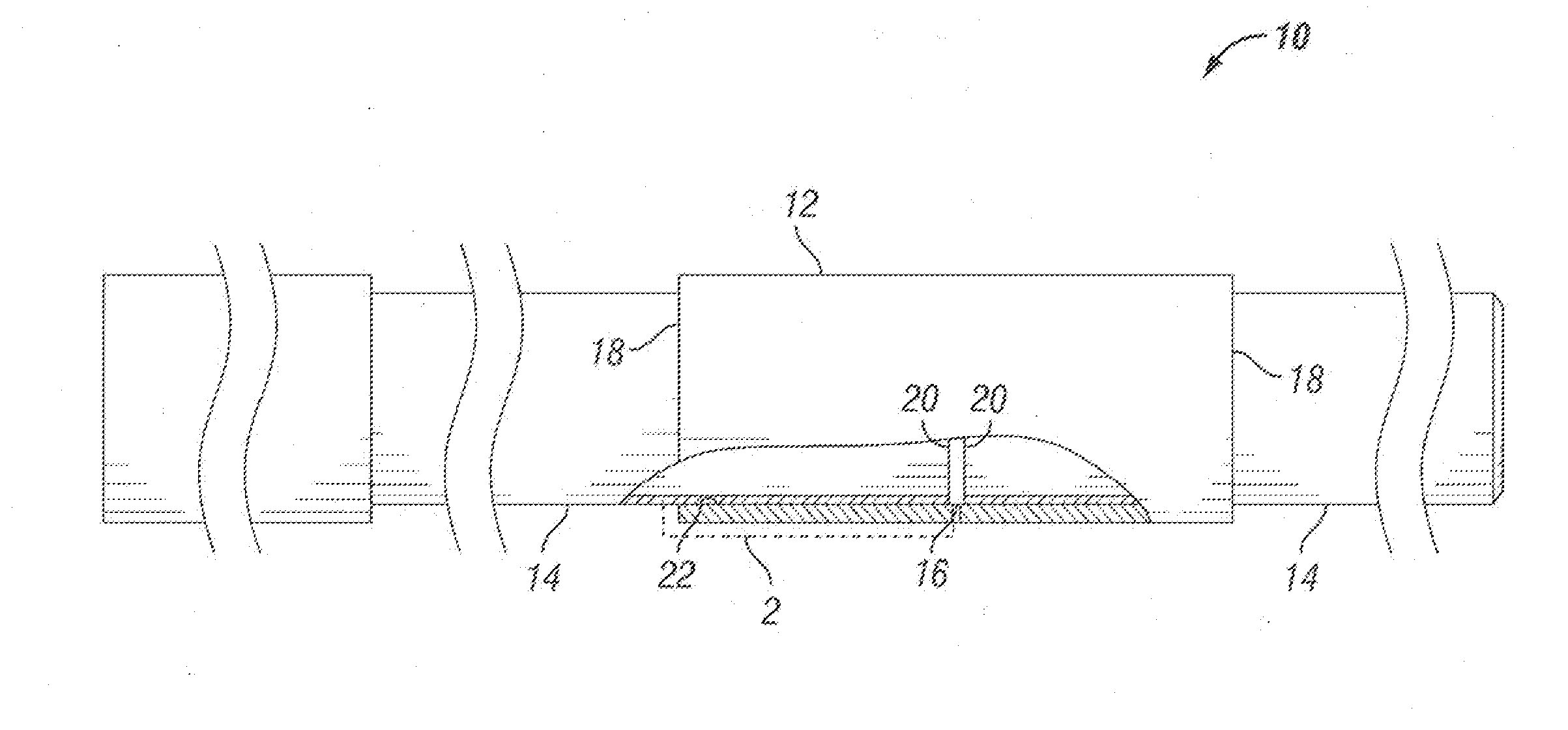
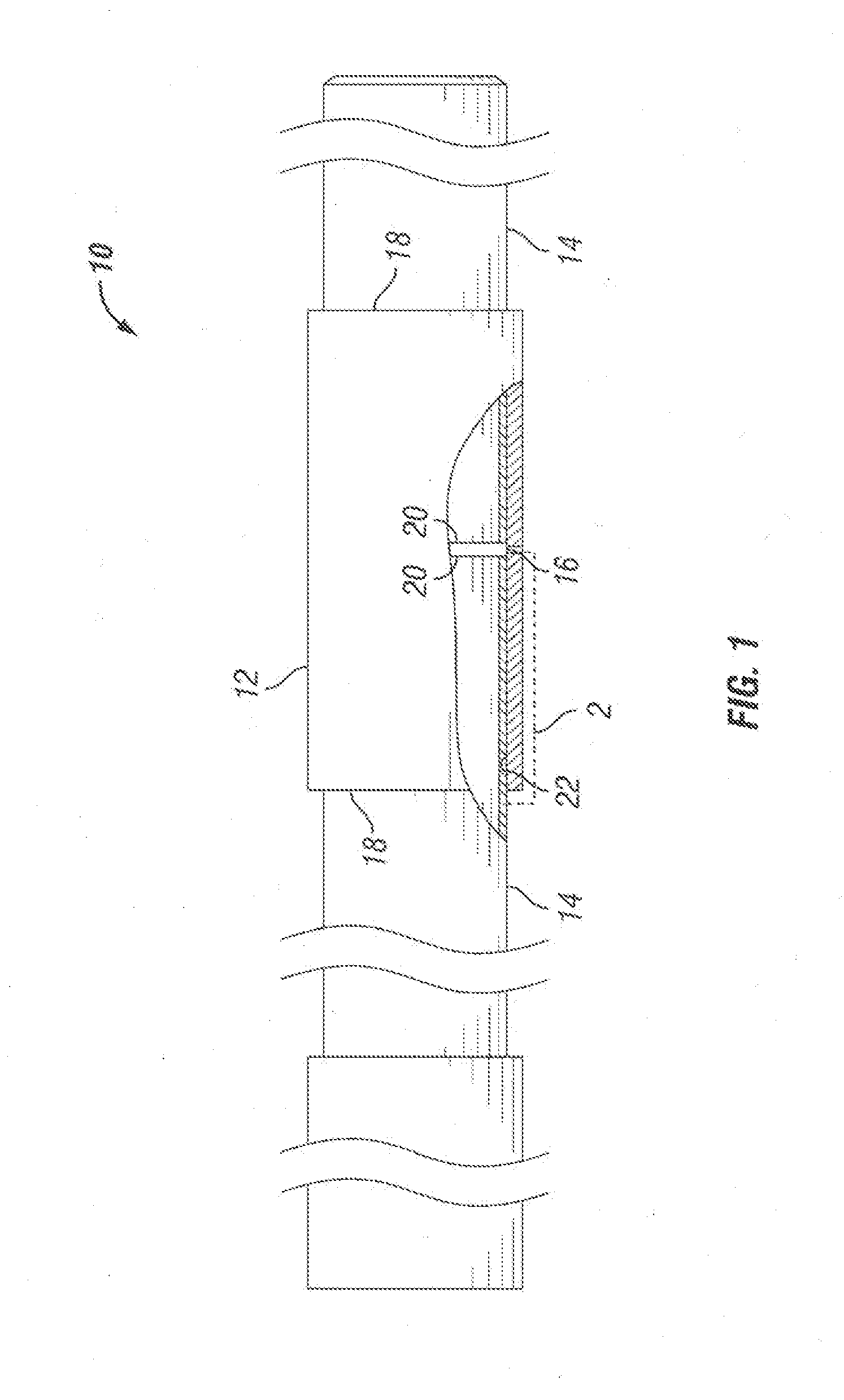
[0039]FIG. 1 is a side partial cross-sectional view of a coupling with pipe assembly 10 according to an embodiment of the present technology. The assembly 10 includes a positive seal coupling 12 and pipe sections 14. The coupling with pipe assembly 10 can also include spacer ring gasket (SRG) 16. In the assembled state, as shown in FIG. 1, t...


PUM

PropertyMeasurementUnit
diameteraaaaaaaaaa
diameteraaaaaaaaaa
stress concentrationsaaaaaaaaaa

Abstract

An apparatus for assembling a positive seal coupling and a pipe, including a frame, a stationary block assembly attached to the frame and having coupling gripping doors, and a traveling block assembly slidably attached to the frame and having pipe gripping doors. Two hydraulic ram cylinders are attached to the frame that have ram cylinder rods attached to the traveling block assembly so that the hydraulic ram cylinders can move the traveling block assembly toward the stationary block assembly. The coupling gripping doors are axially aligned with the pipe gripping doors so that when the hydraulic ram cylinders move the traveling block assembly toward the stationary block assembly, a pipe held by the pipe gripping doors is inserted into a coupling held by the coupling gripping doors.

Description

CROSS REFERENCE TO RELATED APPLICATION[0001]This application claims priority to and the benefit of U.S. Provisional Patent Application Ser. No. 61 / 813,470, which was filed Apr. 18, 2013, the full disclosure of which is hereby incorporated herein by reference.[0002]The present technology relates to the assembly of pipe lines, and in particular to a positive seal coupling for joining pipes without welding, as well as an apparatus for pressing threadless pipe axially into a positive seal coupling to form a string of pipeline.BACKGROUND[0003]Pipes used, for example, in oilfield pipelines, have been joined end-to-end to transport oil or other fluids from place to place. Often, pipelines have been joined by such methods as threading, welding, bolting, and the like. However, problems have developed with each of these pipe joining methods. For example, threaded connections loosen, leading to leaking of fluids from the joints. Connections made by welding, or boiled flanges, are labor intensi...

Claims


Application Information

Patent Timeline
Patent Type & Authority Applications(United States)
IPC IPC(8): F16L1/10
CPCF16L1/10F16L21/022F16L21/08Y10T29/5367Y10T29/49885Y10T29/49826F16L33/224F16L37/105
Inventor LI, JIANMIN
Owner MARUBENI ITOCHU TUBULARS AMERICA
Learn More