Hoist for loading and unloading objects on a truck bed

a truck bed and platform technology, applied in the field of hoists, can solve the problems of unstable ramp, damage to vehicles or other objects being loaded, and injury to persons loading,

Inactive Publication Date: 2007-11-27
DEIST IND LLC
View PDF21 Cites 27 Cited by
  • Summary
  • Abstract
  • Description
  • Claims
  • Application Information

AI Technical Summary

Benefits of technology

[0008]I have invented an improved hoist that will elevate a platform from the ground to an open bed of a truck such as a pickup truck. A vehicle such as a snowmobile, an A.T.V. and a riding mower can be driven onto the platform while the platform is resting solidly on the ground. The driver can then get off the vehicle and the platform. The hoist will then safely elevate the platform, bearing the vehicle resting on the platform and place these onto the open bed of the pickup. The vehicle is then In position to be transported on the pickup. Reversing the action of the hoist allows the vehicle to be unloaded from the pickup.
[0009]Briefly the hoist of my Invention includes a moveable load-bearing platform, a framework adapted to be mounted on the open bed of a truck and having a longitudinally extending stringer; a cantilever arm pivotal relative to the stringer and being pivotally interconnected to the platform; and an actuator which is pivotal relative to the stringer and which, when retracting, causes the cantilever to pivot toward the actuator with resulting raising of the platform. The actuator comprises a longitudinally extending member such as a hydraulic ram. An arrangement of linkages connects the actuator with the cantilever arm to increase the leverage and “reach” of the actuator thereby permitting the actuator to be relatively short in comparison with the travel distance required of the cantilever arm. For example, it is desirable to provide a sufficient movement of the cantilever arm to lower the platform significantly below the truck wheels. This permits loading of watercraft, or of the platform on an irregular surface. The linkage arrangement comprises a first connecting link member interposed between the actuator and the cantilever arm, this first link member being pivotally joined at a first end to the actuator. The second end of the link member is pivotally engaged to the cantilever arm, at a point close to the pivot mount of the cantilever arm to the stringer. A second, generally upstanding anchoring link is pivotally mounted at its lower end to the stringer, at a point between the actuator and the cantilever arm. At its upper end the upstanding link is pivotally joined to the pivot mount joining the actuator and the first link. The actuator and first link form a scissors-like arrangement which unfolds as the actuator extends, thus increasing the “reach” and lifting force of the actuator. The second link serves to maintain longitudinal rigidity of the link system, i.e. to permit the horizontal thrust of the actuator to be transmitted to the cantilever arm.
[0010]In one preferable version, the links are arranged such that they meet at an elbow junction at approximately a 90 degree angle when the actuator and cantilever arm are extended for depositing the platform at ground level. In this position, a retractive force of the actuator may be translated into an upward lifting action of the second link arm acting on the main cantilever arm. The second link arm joins with the cantilever arm at an angle of between 45 and 90 degrees when in this extended position, thereby enhancing the upward lifting and Inertial action of the actuator. This shallow angle is desirable to permit the first link to transfer the weight of the cantilever arm against the frame when the actuator retracts or extends.
[0011]Preferably, the platform includes a at least one roller or wheel mounted at its distal end, to facilitate fore and aft movement of platform as the same as loaded and unloaded. A further desirable feature is fore and aft upstanding members at the respective fore and aft ends of the frame, for elevating and supporting the platform above the truck bed, thus permitting space between the truck bed and the platform for the various linkages and actuator. The rearward (aft) member desirably includes one or more rollers to ease the sliding of the platform over the rearward supporting member.

Problems solved by technology

Loading of the truck bed in this manner can result in damage to the vehicles or other objects being loaded and injury to persons loading them.
If the upper edge overhangs the bumper somewhat, the ramp will become unstable when the weight of the front wheels of the vehicle being loaded is on the overhang.
At this point, the ramp will rock and become unstable and the driver may lose control of the vehicle.
On the other hand, if the upper edge of the ramp overhangs the bumper insufficiently, vibration of the vehicle on the ramp may cause the upper edge to fall off the bumper with resulting damage to the vehicle and Injury to the driver.
Similarly, a heavy load such as a large hay bale is manually loaded onto a truck bed only with great difficulty.

Method used


Image

  • Hoist for loading and unloading objects on a truck bed
  • Hoist for loading and unloading objects on a truck bed
  • Hoist for loading and unloading objects on a truck bed

Examples


Embodiment Construction

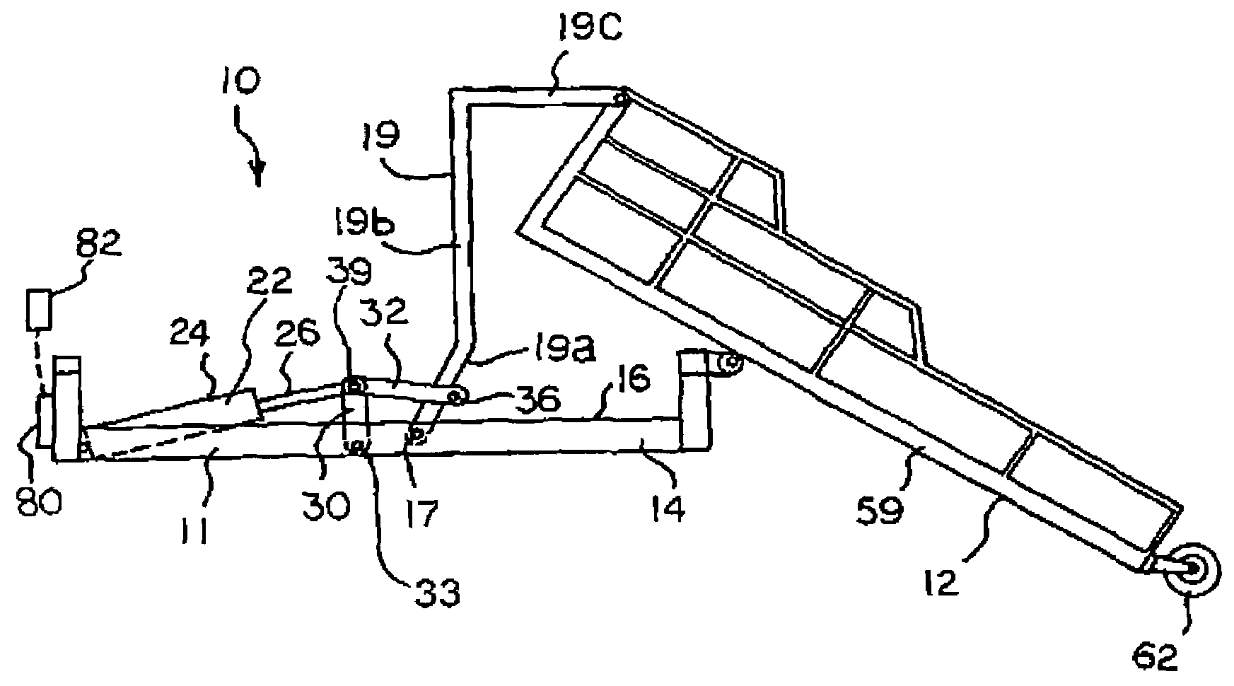
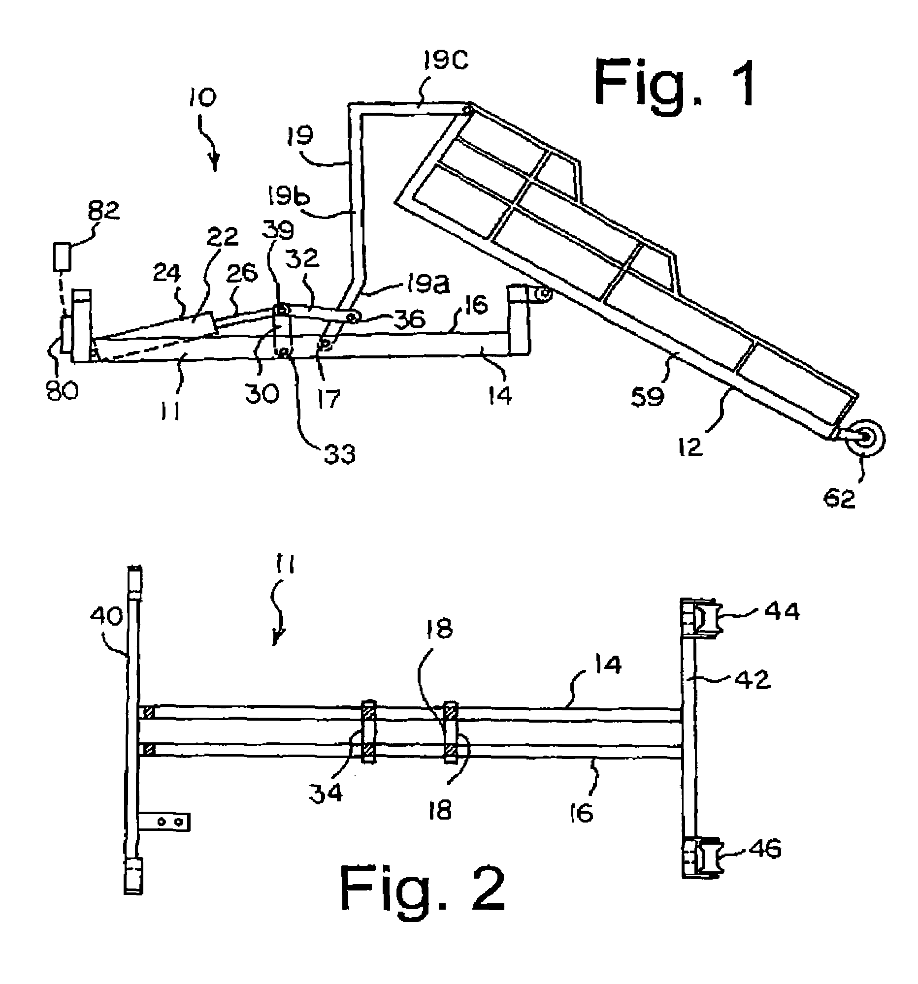
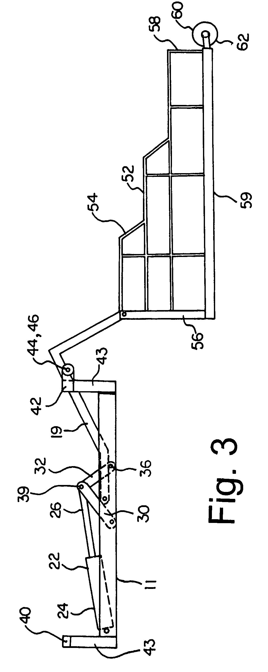
[0025]With reference to FIGS. 1, 2 and 8 the hoist of the invention, generally 10, is shown in conjunction with a platform, generally 12. The hoist has a lower framework 11 which includes a pair of stringers 14, 16, which are fastened to the open bed of a pickup 2 and extend longitudinally from the forward wall of the box adjacent to the cab of the vehicle to the rear edge of the bed. The lower framework is sized to conveniently fit within the bed of a pickup truck. It will be seen that the frame can be scaled up or down in size to permit mounting on a desired vehicle size. The frame is preferably removably mounted by the truck bed, for example by bolting to the truck bed. The invention is illustrated and described herein in association with a conventional pickup truck. It will be understood that any vehicle having a suitable bed will accommodate the invention.

[0026]As illustrated in FIGS. 7 and 8, the rear gate of the pickup 2 is removed to accommodate the hoist and platform of the...


PUM


Abstract

A hoist for elevating cargo onto the bed of a truck includes a frame (11) which may be mounted to the truck bed, a platform or container (12) which is connected to the frame by a pivoting arm (9), and an arrangement of linkages for rotating the arm (9) to position the platform either on the truck bed or on a loading and unloading position resting on the ground behind the truck. A hydraulic ram (24) is connected to the arm (9) via the linkages, with the linkages being arranged to increase the effective “flow” of the arm to provide a long travel distance of the arm.

Description

FIELD OF THE INVENTION[0001]This invention relates to hoists and more particularly to a hoist for elevating a load-bearing platform from the ground to an open bed of a pickup truck and for returning the platform to the ground.BACKGROUND OF THE INVENTION[0002]Pickup trucks and other vehicles having a cargo-carrying bed are commonly used to transport loads which are too heavy to be manually hoisted, for example, a user might wish to load a small and light vehicle such as a snowmobile, all terrain vehicles (“A.T.V.”) or riding lawn mowers. Such loads are usually loaded onto the truck by pushing or driving them up a ramp and onto the open bed of the truck. Loading of the truck bed in this manner can result in damage to the vehicles or other objects being loaded and injury to persons loading them. An example is the case of loading a vehicle onto a truck bed, using a ramp. The upper edge of the ramp must typically rest solidly on the rear bumper of the truck while the vehicle is being dri...

Claims


Application Information

Patent Timeline
IPC IPC(8): B60P1/00B65F3/00B60P1/64B60P3/42
CPCB60P3/42B60P1/6463
Inventor BENEDIKT, WILHELM ALFRED
Owner DEIST IND LLC
Why Eureka
Try Eureka