
syringe

Active Publication Date: 2014-10-16
SUZUKEN
View PDF1 Cites 7 Cited by
  • Summary
  • Abstract
  • Description
  • Claims
  • Application Information

AI Technical Summary

Benefits of technology

The present invention provides a syringe with an elastic member that can be easily assembled in advance without reducing the efficiency of assembly. The syringe has a seat that is held in a compressed state and released during use to safely house the injection needle. The elastic member is released from the seat when the operational part is operated in a certain direction after the injection. The syringe is cost-effective and easy to assemble. The technical effects of the invention include improved assembly efficiency, reduced product cost, and improved safety during use.

Problems solved by technology

However, the aforementioned conventional syringe having the automatic housing function for the injection needle encounters the following problem.
Hence, for assembly of the needle retaining member, assembling work should be accompanied by compressing the spring gradually, so that favorable workability of assembly might become unfeasible.

Method used


Image

  • syringe
  • syringe
  • syringe

Examples


working example 1

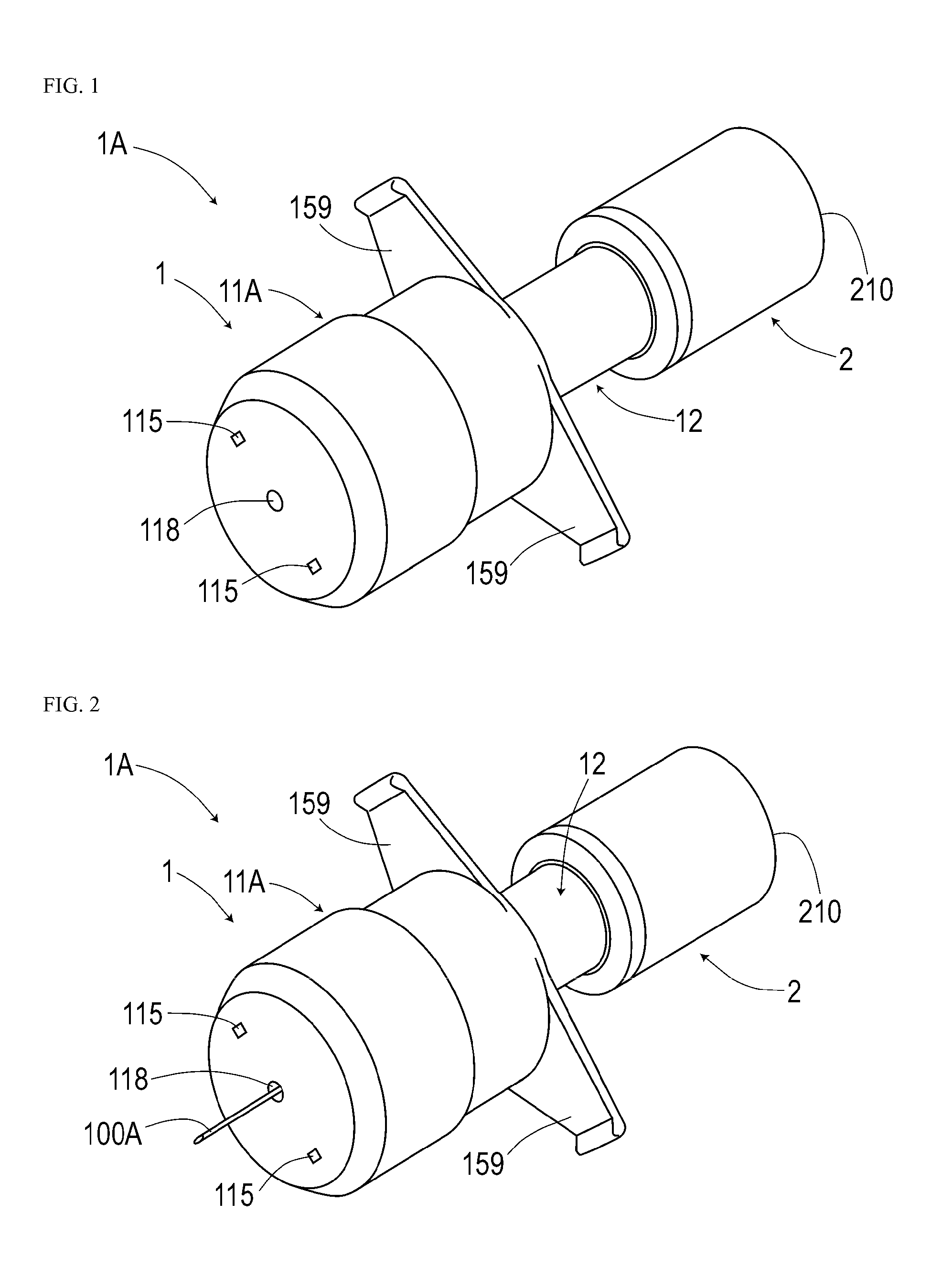
[0046]The present example relates to a disposable pre-filled syringe 1A (a syringe that is already filled with a drug solution). Specifics of this pre-filled syringe 1A will be described below with reference to FIGS. 1 to 17.

[0047]As shown in FIGS. 1 to 3, the pre-filled syringe 1A according to the present example has a vial 2 (drug solution container), a gasket 25 (closing member), and a needle unit 1 (needle housing unit). The vial 2 has a shape of a cylinder with a bottom and is filled with the drug solution. The gasket 25 closes an opening in a manner movable in the boring direction of the cylindrical shaped vial 2 so as to push the drug solution out. The needle unit 1 is attached to the gasket 25. The pre-filled syringe 1A in a manufactured state has a total length of approximately 80 mm, and a maximum diameter of approximately 17 mm excluding finger grips 159. A syringe could be easy to handling in case the total length of approximately 60-100 mm and the maximum diameter of ap...

second working example

[0100]The present example is based on the pre-filled syringe of the first working example. The present example facilitates automation of action to be taken after injection. Specifics of this pre-filled syringe will be described below with reference to FIG. 18.

[0101]The pre-filled syringe of the present example differs from the spring of the first working example. A spring 18 of the present example is prohibited from rotating while being turned in a rotation direction and is held by the first holder member 11A in this state. The spring 18 has projecting ends 181 and 182 axially projecting at its opposite ends formed by bending winding ends of the spring 18. The projecting ends 181 and 182 are prohibited from rotating while in engagement with side surfaces of the seats 153A and 155A. The rotation direction where the spring 18 is turned corresponds to a direction where rotation elastic force is accumulated to be applied to bias the second holder member 12 in the right rotation directio...

third working example

[0105]The present example describes an example of a syringe 1B employing a needle cover as an application of the first holder member of the first working example. Specifics of this syringe will be described below with reference to FIGS. 19 and 20.

[0106]The needle cover 11B of the present example is a member formed by removing a slider portion (symbol 110 in FIG. 7) from the first holder member (symbol 11A in FIG. 7) of the first working example, extending the resultant first holder member in the axial direction, and providing a fall prevention portion 158 to the inner circumferential surface at an open end. A syringe body 1C to be combined with the needle cover 11B is a syringe used for injecting a drug solution in a solution chamber by pushing a plunger (operational part) 32 into an injection cylinder 31. A projecting portion 310 responsive to the fall prevention portion 158 is provided in the outer circumferential surface of the injection cylinder 31.

[0107]A drug solution can be i...


PUM


Abstract

A syringe (1B) comprises: a syringe body (1C) including a plunger (32) to be operated for injection of a drug solution; a cylindrical needle cover (11B) housing an injection needle (100A); and a spring (18) held in a compressed state by the needle cover (11B). The needle cover (11B) has seats (153A) and (155B) in a pair that abut on corresponding opposite ends of the spring (18) to restrict the position of the spring (18). Pushing in the plunger (32) further after injection deforms the seat (155A) to release restriction on the spring (18). The spring (18) free from the restriction abuts on the syringe body (1C). This biases the needle cover (11B) to move the needle cover (11B) to a position where the injection needle (100A) is housed.

Description

TECHNICAL FIELD[0001]The present invention relates to a syringe having a housing function for an injection needle.BACKGROUND ART[0002]Various types of syringes are used for medical practices in medical facilities such as hospitals. Plastic disposable syringes have become mainstream recently. A syringe of this type that is used most commonly has a removable cap covering an injection needle. Keeping the injection needle covered with the cap until injection is started can prevent injuries and the like due to needlestick accidents before they occur. Covering the injection needle with the cap after the injection can prevent needlestick accidents and the like to occur during disposal of the syringe. The injection needle might be contaminated with a virus or the like infecting a patient after the injection, so that needlestick accidents should be prevented reliably particularly in such a case.[0003]A syringe having an automatic housing function for an injection needle (needle) has been sug...

Claims


Application Information

Patent Timeline
IPC IPC(8): A61M5/32A61M5/315A61M5/28
CPCA61M5/158A61M5/28A61M5/315A61M2005/3247A61M5/326A61M5/3271A61M5/32A61M2005/3263
Inventor SUZUKI, ICHIRO
Owner SUZUKEN
Learn More