
Method of detecting presence of interference source, and touch sensing system

a touch sensing system and source technology, applied in the field of detecting the presence of an interference source, can solve the problems of affecting the stability of electronic components to which the conventional touch sensing device outputs the trigger signal, affecting the accuracy of touch events, so as to prevent touch events from being misjudged

Active Publication Date: 2014-10-16
ENETECH
View PDF13 Cites 11 Cited by
  • Summary
  • Abstract
  • Description
  • Claims
  • Application Information

AI Technical Summary

Benefits of technology

The present invention provides a method for detecting an interference source in a touch sensing system to prevent incorrect touch event detection. This method can be implemented in a touch sensing system to prevent misjudgments of touch events.

Problems solved by technology

However, in the presence of interference (e.g., electrostatic discharge or radiation noise from other electronic apparatuses), the capacitance value generated by the sensed signal processor may fluctuate drastically and undesirably exceed the predetermined threshold value.
Under severe circumstances, stability of electronic components to which the conventional touch sensing device outputs the trigger signal may be compromised.
However, although the abovementioned improvements are effective to a certain extent, they may suffer from other drawbacks.
For example, the dimensions of the grounding copper foil may not be adjusted dynamically based on intensity and duration of interference detected by the conventional touch sensing device.
Moreover, reducing the gaps among the components may result in a substantial change in appearance of the conventional touch sensing device, which may lead to compromised aesthetics.
Furthermore, the abovementioned improvements may increase cost of manufacture.

Method used


Image

  • Method of detecting presence of interference source, and touch sensing system
  • Method of detecting presence of interference source, and touch sensing system
  • Method of detecting presence of interference source, and touch sensing system

Examples


Embodiment Construction

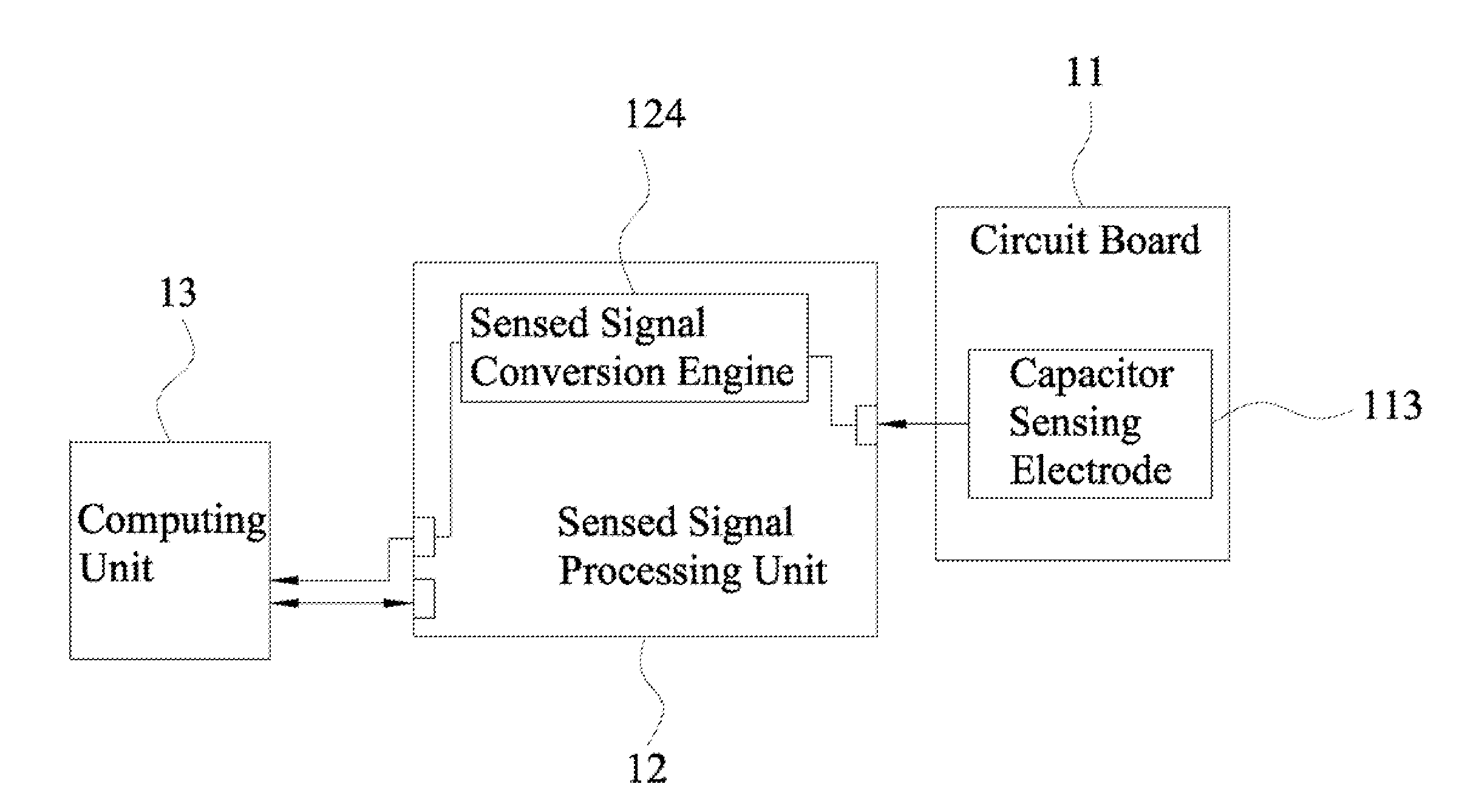
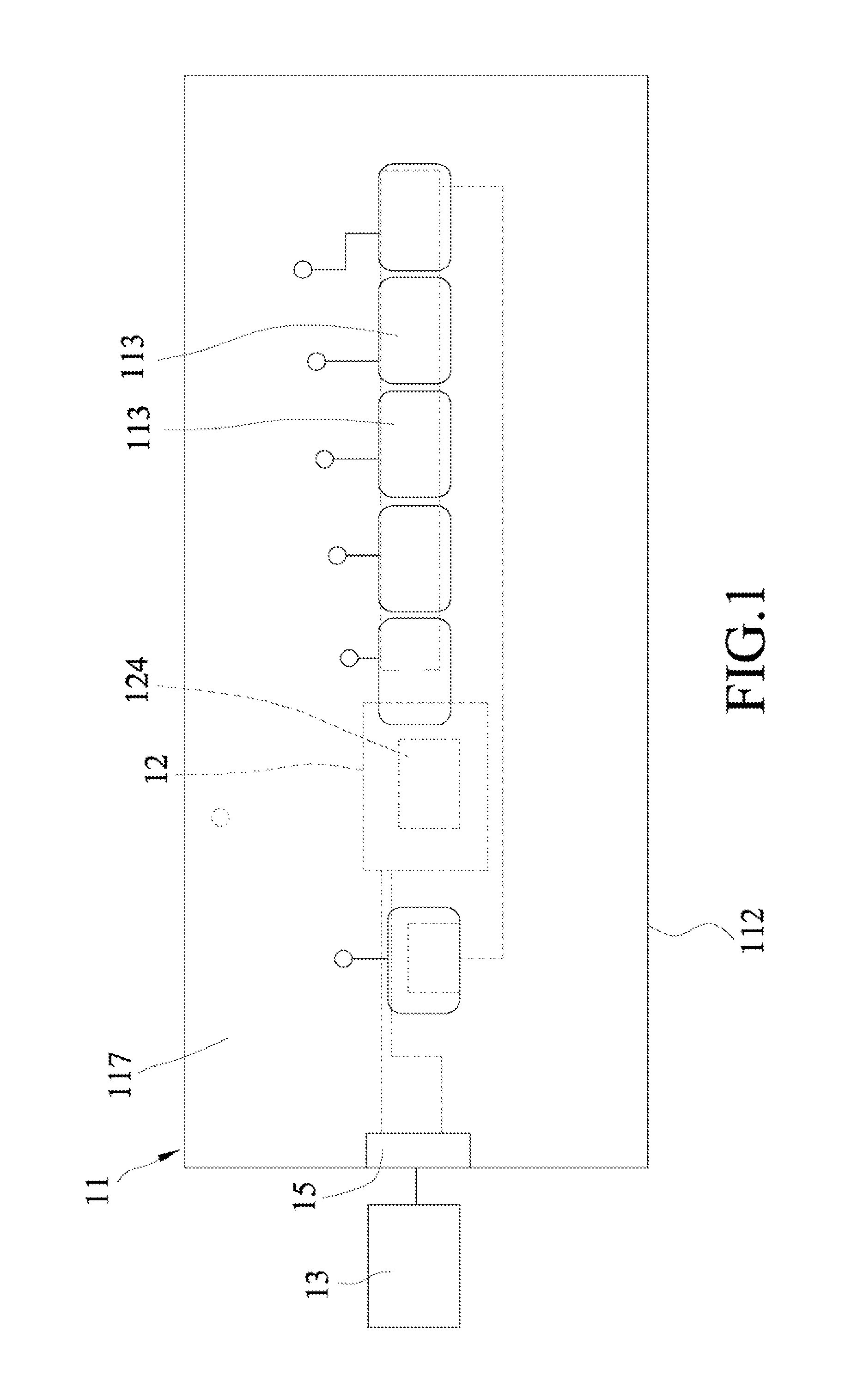
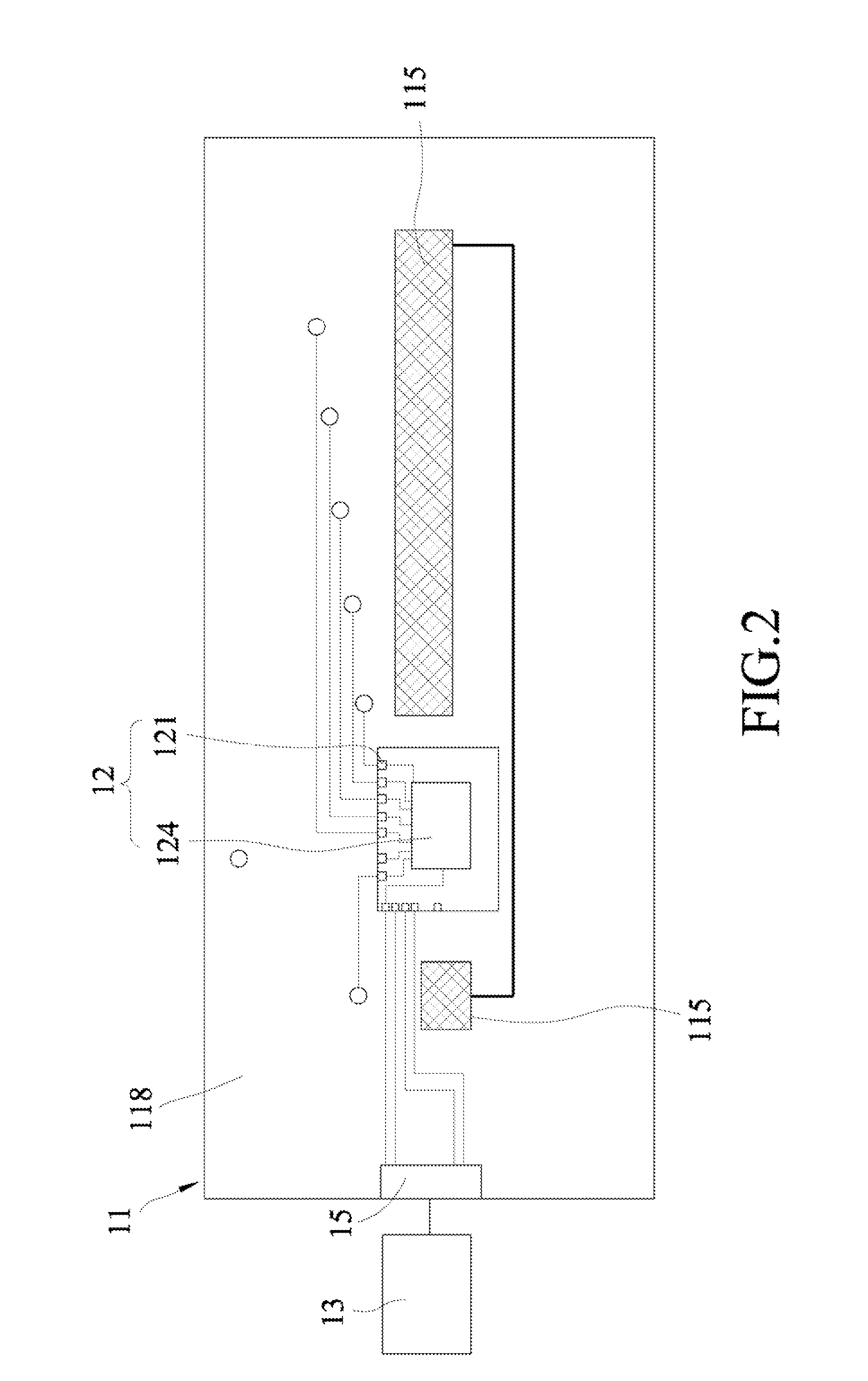
[0029]Referring to FIGS. 1 to 3, the first preferred embodiment of the touch sensing system according to this invention is shown to comprise a touch sensing device that includes a circuit board 11 and a sensed signal processing unit 12 (which cooperates with the circuit board to form a touch control unit), and a computing unit 13 that is a component separate from the touch sensing device, that is coupled electrically to the sensed signal processing unit 12 and that stores a threshold capacitance difference. In other embodiments, the computing unit 13 may be integrated with the sensed signal processing unit 12.

[0030]The circuit board 11 includes a dielectric substrate 112, a plurality of capacitor sensing electrodes 113, and a grounding conductive layer 115. The dielectric substrate 112 has a first surface 117 having a first region, and a second surface 118 opposite to the first surface 117 and having a second region overlapping with a projection of the first region onto the second s...


PUM


Abstract

A method for detecting presence of an interference source is to be performed by a touch sensing system that stores a threshold capacitance difference. The method includes the steps of sampling capacitances periodically within a time period for obtaining a base capacitance value; sensing a comparison capacitance after the time period; computing an absolute difference between the comparison capacitance and the base capacitance value; and determining that the interference source is present when the comparison capacitance is smaller than the base capacitance value and the absolute difference is greater than the threshold capacitance difference.

Description

CROSS-REFERENCE TO RELATED APPLICATION[0001]This application claims priority to Taiwanese Application No. 102113452, filed on Apr. 16, 2013.BACKGROUND OF THE INVENTION[0002]1. Field of the Invention[0003]The invention relates to a method for detecting presence of an interference source, and more particularly to a method for detecting presence of an interference source and performed by a touch sensing system.[0004]2. Description of the Related Art[0005]A conventional touch sensing device includes a touch sensor unit (e.g., a touch button), and a sensed signal processor operatively associated with the touch sensor unit for sensing external environment so as to generate a capacitance value. When the capacitance value thus generated exceeds a predetermined threshold value, the sensed signal processor generates a trigger signal for notification of a touch event.[0006]The conventional touch sensing device is able to function normally when used in an environment that has certain temperatur...

Claims


Application Information

Patent Timeline
Patent Type & Authority Applications(United States)
IPC IPC(8): G06F3/044
CPCG06F3/044G06F3/0445
Inventor LEE, CHAO-MING
Owner ENETECH
Learn More