Method and apparatus for carding of staple fibers

a staple fiber and carding technology, applied in the field of method and apparatus of carding staple fibres, can solve the problems of high stress on the fibre, significant damage to the fibre, and weakened fibres, and achieve the effects of selective enhancement of fiber movement and trash movement in the entrained air, damage due to pin impact, and selective enhancement of fiber movement and trash movemen

Inactive Publication Date: 2014-10-16
LAKSHMINARAYAN KANNAN
View PDF10 Cites 7 Cited by
  • Summary
  • Abstract
  • Description
  • Claims
  • Application Information

AI Technical Summary

Benefits of technology

[0051]It is another aspect of the present invention, wherein damage due to the impact of pins of the said carding cylinder on the fibers gripped in the said feeding arrangement is reduced by positioning the said feed-table before the said feed-roller, with respect to the direction of approach of pins of the said carding cylinder.
[0052]It is another aspect of the present invention, wherein intended movement of the fibers and trash in the entrained air is selectively enhanced by the application of suction.
[0053]It is another aspect of the present invention, wherein intended movement of the fibers and trash in the entrained air is selectively enhanced by the application of blowing air.
[0054]It is another aspect of the present invention, wherein uniformity of the web is enhanced by the successive deposition of multiple layers of fibers on the surface of the perforated roller, by rotating the said perforated roller at slow peripheral speed in relation to that of the said carding cylinder.
[0055]It is another aspect of the present invention, wherein uniformity of the web is enhanced by successive deposition of successive layers of fibers on the surface of the perforated roller, preferentially in areas with lesser densities of deposition, on account of reduced flow resistance leading to stronger air-currents directing fibers towards those regions.
[0056]It is another aspect of the present invention, wherein uniformity of the web is enhanced by setting the at least one air-deflecting element at a farther setting from the said carding cylinder, so that a greater number of fibers re-circulate, building up a reserve-stock of re-circulating fibers that smoothen momentary variations in rate of feed of fibers.

Problems solved by technology

These features render the fibres vulnerable to breakage, apart from requiring high precision in manufacture and setting of the clearance between the nose and the licker-in cylinder.
Either the machine has to be stopped periodically for this or a complicated and costly arrangement of “revolving flats” is used so that the flats can be cleaned without stopping the machine.
Also, the fibres experience high stresses due to the mechanical action in various parts.
This leads to significant damage to the fibre, which loses several desirable properties it possesses in its natural state.
This poses formidable challenges in manufacturing and therefore impact the cost of the carding machine.
Moreover a well-known challenge in carding is the problem of re-circulating fibres—fibres that circulate multiple times around the cylinder because of inefficient doffing.
These fibres reduce the effective area available on the carding cylinder for fresh fibres that are fed, necessitating a reduced feed rate to compensate for it, thereby reducing the machine productivity.
However, forced draught of air requires substantial power, apart from greater complexity in construction in order to provide leak-free enclosures and ducts.
It is obvious that all these methods come with significantly increased complexity, costs and performance overheads.
The need to selectively remove short fibres before carding has been an issue of significant importance, because short fibres choke the carding flats and reduce the efficacy of their action.
While such inventions are directed at improving the performance of the carding machine by adding additional components, it is also recognized that the machine is very bulky, heavy and entails expensive manufacturing operations to achieve acceptable levels of precision.

Method used


Image

  • Method and apparatus for carding of staple fibers
  • Method and apparatus for carding of staple fibers
  • Method and apparatus for carding of staple fibers

Examples


Embodiment Construction

[0061]With respect to the drawings it is to be understood that only enough of the construction of the invention and the surrounding environment in which the invention is employed have been depicted therein, in order to simplify the illustrations, as needed for those skilled in the art to readily understand the underlying principles and concepts of the invention.

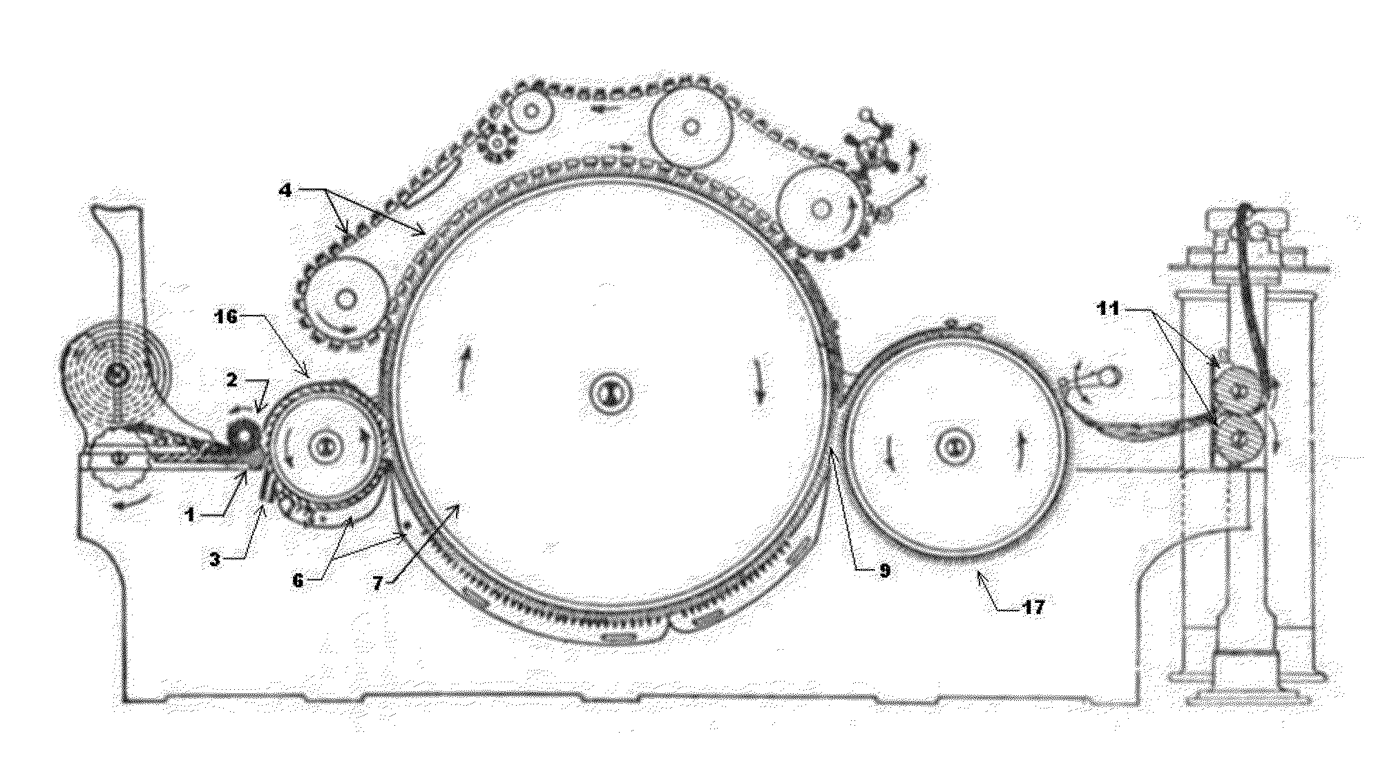
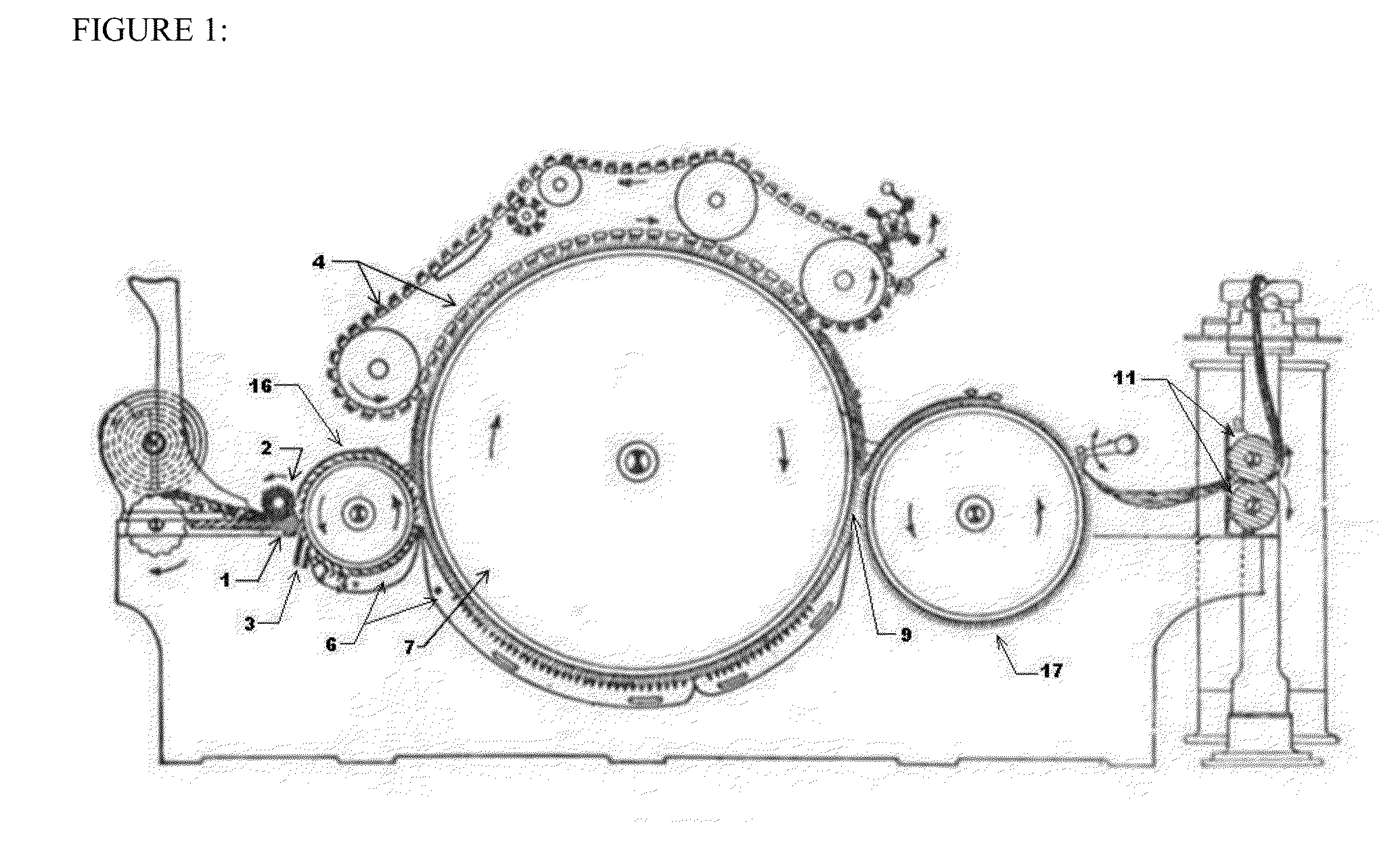
[0062]FIG. 1 shows, in schematic form, a prior art for the conventional carding apparatus. The tufts of fibres in the form of lap is guided by the feeding arrangement comprising stationary feed table 1 and rotatable feed roller 2 to a licker-in roller 16. The tufts of fibres that are firmly gripped between feed table 1 and feed roller 2 are stripped off by the pins of the licker-in cylinder 16 which rotates at a surface speed higher than that of the feed roller 2 resulting in opening of the tufts. The tufts are then passed on to the carding cylinder 7 from the licker-in cylinder 16. The revolving flats 4 in co-operation with ...


PUM

PropertyMeasurementUnit
diameteraaaaaaaaaa
densityaaaaaaaaaa
diameteraaaaaaaaaa

Abstract

The present invention relates to a method and apparatus of carding staple fibres like cotton. More particularly, the present invention is directed to an apparatus for carding of staple fibres with minimum number of moving parts and to reduce the need for close tolerances, especially where moving parts are involved, in order improve the manufacturability of the apparatus. Density of input tufts to the carding machine is reduced. Diameter of carding cylinder (7) is reduced, with corresponding increase in its rotational speed, to maintain the peripheral speed. An air guiding element (6) and at least air deflection elements (8) used for capturing long fibres on a perforated roller. This enables elimination of close-set moving parts and simplifications of design. Advantageously, the present invention minimizes the damage to the fibres so that they retain their natural and desirable properties.

Description

FIELD OF INVENTION[0001]The present invention relates to a method and apparatus of carding staple fibres like cotton. More particularly, the present invention is directed to an apparatus for carding of staple fibres with minimum number of moving parts and to reduce the need for close tolerances, especially where moving parts are involved, in order to improve the manufacturability of the apparatus. Advantageously, the present invention minimizes the damage to the fibres so that they retain their natural and desirable properties.DESCRIPTION OF PRIOR ART[0002]Carding is a process that takes tufts of fibres as input, removes the trash and short fibres contained in them and individualizes the fibres to finally deliver a uniform web of these individualized fibres.[0003]In conventional carding machines, the tufts of fibres are fed to the apparatus by a cylindrical rotating member termed as feed-roller and a specially contoured stationary member termed as feed-table that presses against the...

Claims


Application Information

Patent Timeline
Patent Type & Authority Applications(United States)
IPC IPC(8): D01G15/08
CPCD01G15/40D01G15/08D01G15/80
Inventor LAKSHMINARAYAN, KANNAN
Owner LAKSHMINARAYAN KANNAN
Why Eureka
Try Eureka