
Fluid transfer seal assemblies, fluid transfer systems, and methods for transferring process fluid between stationary and rotating components using the same

a technology of fluid transfer seals and fluid films, applied in the direction of engine seals, blade accessories, engine components, etc., can solve the problems of high leakage rate, high leakage rate, and inability to achieve close clearance dimensional controls, so as to facilitate process fluid transfer, and promote positive fluid film stiffness

Inactive Publication Date: 2014-10-09
HONEYWELL INT INC
View PDF6 Cites 5 Cited by
  • Summary
  • Abstract
  • Description
  • Claims
  • Application Information

AI Technical Summary

Benefits of technology

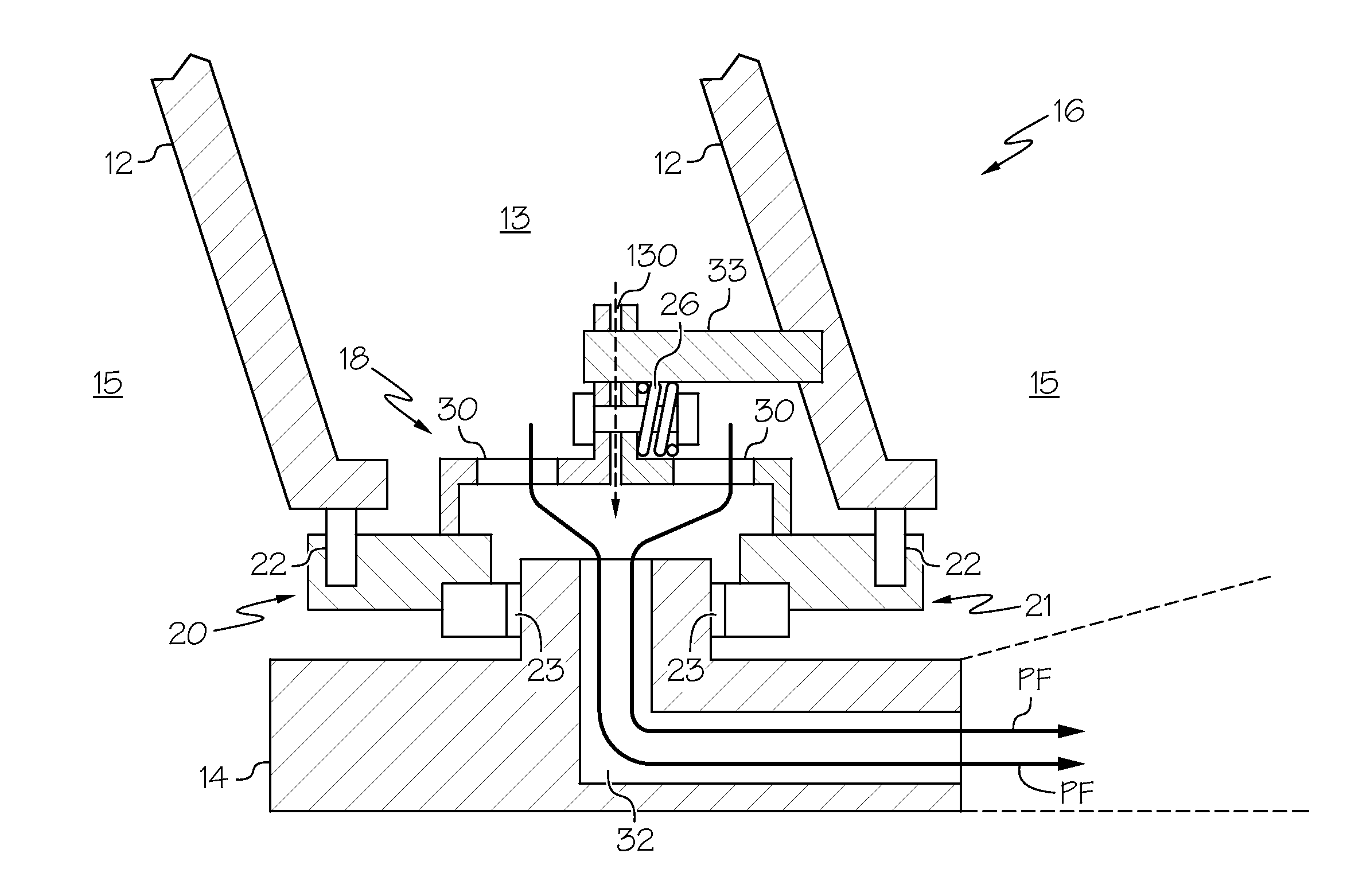
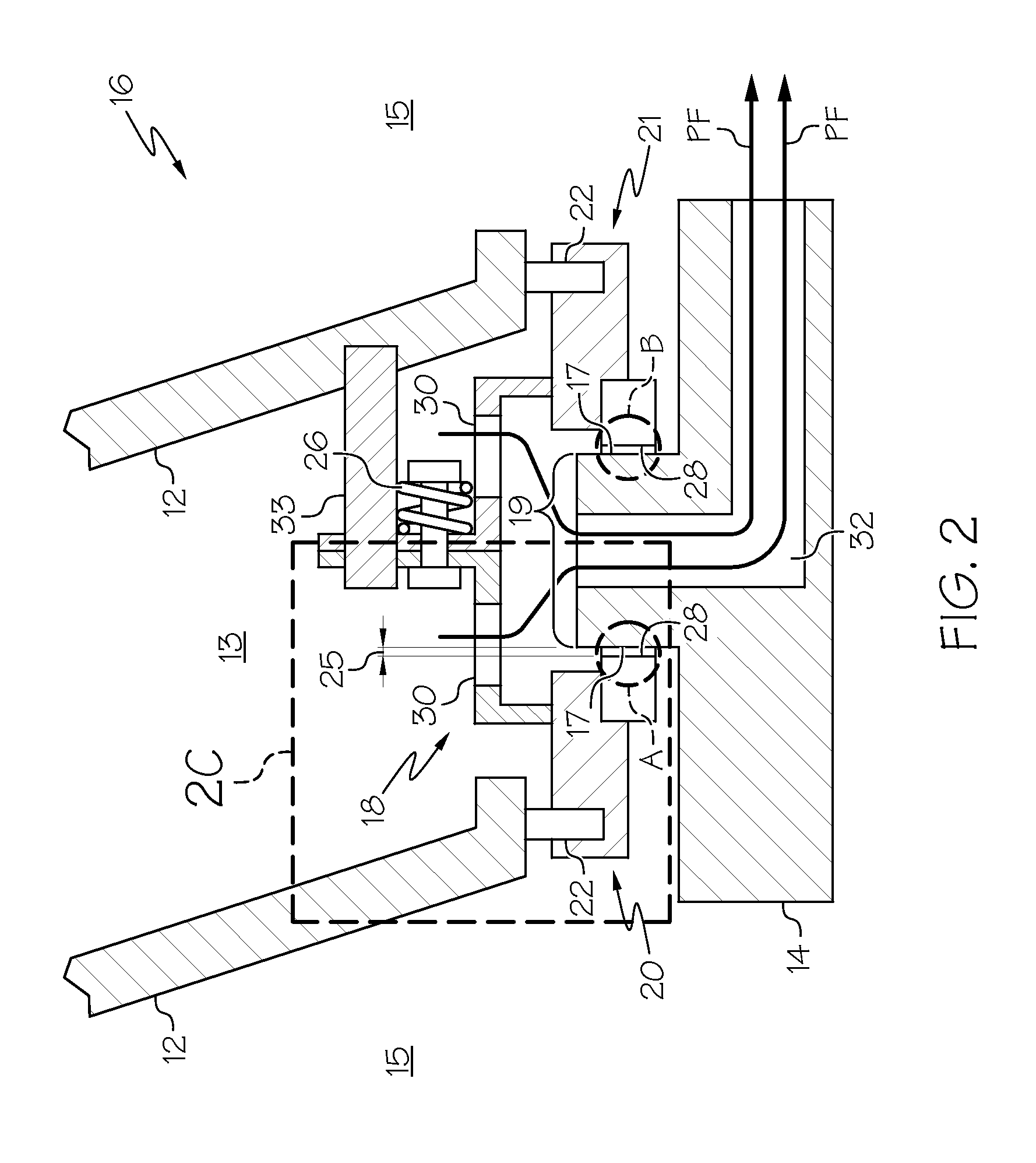
This patent describes a seal assembly for transferring process fluid between a stationary and a rotating component. The seal assembly consists of a face seal ring and a secondary seal. The face seal ring has a fluid passageway and a sealing face that forms a hydrodynamic seal with the sealing surface of the rotating component. The secondary seal is positioned between the face seal ring and the stationary component. This seal assembly helps to prevent leakage of process fluid during rotation and ensures safe transfer of process fluid from the stationary component to the rotating component.

Problems solved by technology

However, these mechanical seals may themselves leak and generate excessive heat.
Journal type seals have been used for low speed, liquid transfer applications, but may also result in high leakage rates and require close clearance dimensional controls.
The transfer of cooling air (a process fluid) from a stationary tangential on-board injector (TOBI) to the rotating turbine of a gas turbine engine is one example of such an application where conventional mechanical seals have not adequately reduced process fluid leakage or ingestion.
Unfortunately, some of the cooling air discharged from the TOBI is leaked through the seals, resulting in an adverse effect on TOBI performance.
More specifically, leakage of the cooling air from the TOBI results in less cooling air going to the turbine for cooling, thereby causing the turbine to run hotter and shortening its life.
If extra cooling air is supplied to compensate for leakage to preserve turbine life, engine performance including fuel consumption and power may be compromised.
Other applications requiring that a process fluid be controllably transferred across an interface between a stationary component and a rotatable component in rotating equipment are similarly adversely affected by process fluid leakage or ingestion that is not adequately prevented by conventional mechanical seals.

Method used


Image

  • Fluid transfer seal assemblies, fluid transfer systems, and methods for transferring process fluid between stationary and rotating components using the same
  • Fluid transfer seal assemblies, fluid transfer systems, and methods for transferring process fluid between stationary and rotating components using the same
  • Fluid transfer seal assemblies, fluid transfer systems, and methods for transferring process fluid between stationary and rotating components using the same

Examples


Embodiment Construction

[0021]The following detailed description is merely exemplary in nature and is not intended to limit the invention or the application and uses of the invention. As used herein, the word “exemplary” means “serving as an example, instance, or illustration.” Thus, any embodiment described herein as “exemplary” is not necessarily to be construed as preferred or advantageous over other embodiments. All of the embodiments described herein are exemplary embodiments provided to enable persons skilled in the art to make or use the invention and not to limit the scope of the invention which is defined by the claims. Furthermore, there is no intention to be bound by any expressed or implied theory presented in the preceding technical field, background, brief summary, or the following detailed description.

[0022]Various embodiments are directed to fluid transfer seal assemblies, fluid transfer systems, and methods for transferring process fluid between stationary and rotating components using the...


PUM


Abstract

Fluid transfer seal assemblies for transferring process fluid between a stationary component and a rotating component, fluid transfer systems, and methods for transferring process fluid between the stationary and rotating components via a fluid transfer assembly are provided. A rotatable component includes a sealing surface. The fluid transfer seal assembly comprises a face seal ring having at least one segment of a fluid passageway and a sealing face configured to be disposed opposite of the sealing surface. The sealing face or the opposed sealing surface includes a geometric feature for forming a hydrodynamic seal therebetween. A secondary seal is configured to be disposed between and contacting the face seal ring and the stationary component.

Description

TECHNICAL FIELD[0001]The present invention generally relates to gas turbine engines, and more particularly relates to fluid transfer seal assemblies, fluid transfer systems, and methods for transferring process fluid between stationary and rotating components using the same.BACKGROUND[0002]There are many applications requiring that a process fluid be controllably transferred across an interface between a stationary component and a rotatable component in rotating equipment having at least one component which is rotatable with respect to at least one other adjacent component. Depending upon whether or not the transferred process fluid is at higher or lower pressure than the surroundings, this fluid transfer involves some process fluid leakage or ingestion. Minimizing the process fluid loss or ingestion is important for maintaining rotating equipment performance. As used herein, the term “process fluid” refers to any fluid that is used as the primary working fluid in a device, system, ...

Claims


Application Information

Patent Timeline
Patent Type & Authority Applications(United States)
IPC IPC(8): F02C7/28F01D11/02
CPCF01D11/02F02C7/28F01D5/081F01D11/025F16J15/3484F01D11/04F16J15/342F16J15/40F16J15/3244F16J15/4472F16J15/3448F16J15/4476
Inventor O'BRIEN, MICHAEL
Owner HONEYWELL INT INC
Learn More