
Multi-joint robot having gas spring, and method for estimating inner pressure of the gas spring

a multi-joint robot and gas spring technology, applied in the direction of programmed manipulators, instruments, programme control, etc., can solve the problems of robot to be brought to an emergency stop, increase the cost of equipment, and gradually decrease the inner pressure of the cylinder

Active Publication Date: 2014-10-02
FANUC LTD
View PDF3 Cites 20 Cited by
  • Summary
  • Abstract
  • Description
  • Claims
  • Application Information

AI Technical Summary

Benefits of technology

The present invention provides a method to estimate the decrease in inner pressure of a gas spring of a multi-joint robot. This is important because the gas spring helps reduce the load on the servomotor that drives the arm. The method involves measuring the current value of the servomotor at two different times and calculating the difference between them. This difference tells us about the amount of decrease in pressure of the gas inside the spring. The technical effect of this invention is to improve the accuracy and efficiency of the robot's control system.

Problems solved by technology

On the other hand, in the gas spring, it is known that gas enclosed in the cylinder may leak to the outside the cylinder due to the motion of the piston rod relative to the cylinder, whereby the inner pressure of the cylinder gradually decreases.
Therefore, the force generated by the balancer is lowered, resulting in an alarm informing of a lack of torque being output, thereby causing a robot to be brought to an emergency stop.
As described in JP 2007-298513 A or JP 2009-270987 A, when the pressure indicator is attached to the outside of the gas spring, the cost of equipment is increased, based on the cost of the pressure indicator.
However, use of the connecting means increases the possibility of gas leakage.
Further, gas leakage may occur due to breakage of the pressure indicator.

Method used


Image

  • Multi-joint robot having gas spring, and method for estimating inner pressure of the gas spring
  • Multi-joint robot having gas spring, and method for estimating inner pressure of the gas spring
  • Multi-joint robot having gas spring, and method for estimating inner pressure of the gas spring

Examples


Embodiment Construction

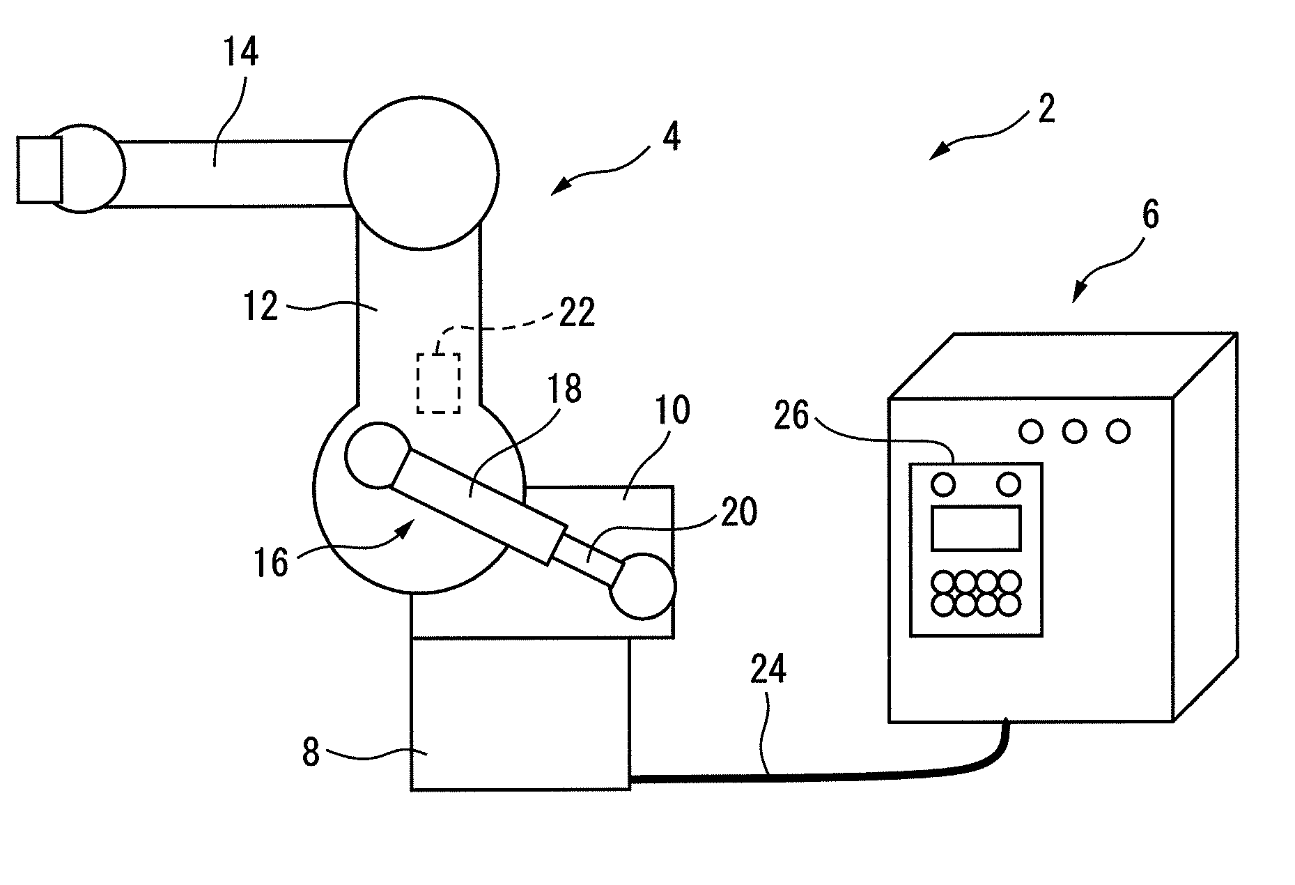
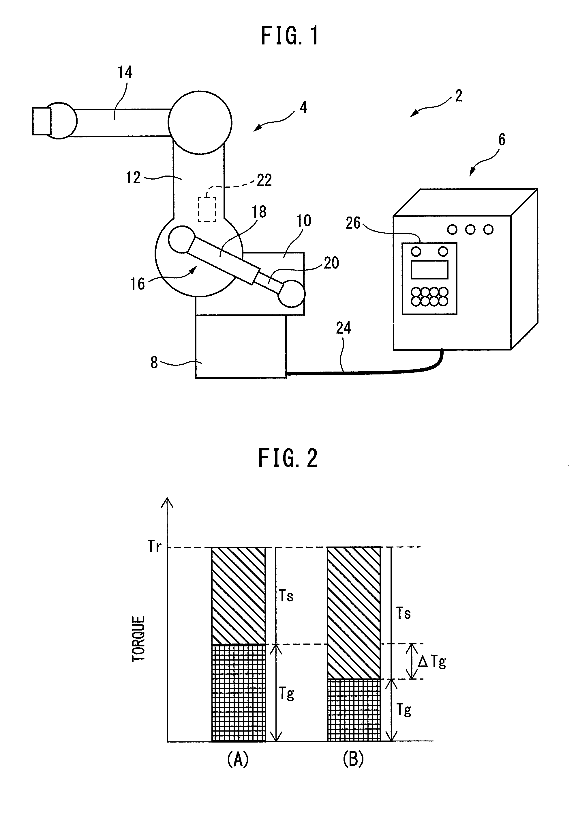
[0023]FIG. 1 shows a schematic configuration of a multi-joint robot according to a preferred embodiment of the present invention. Multi-joint robot 2 includes a robot mechanical unit 4 having at least one arm 12, a controller 6 which controls robot mechanical unit 4, and a gas spring arranged on the at least one arm. In the illustrated embodiment, robot mechanical unit 4 has a base 8, a rotating body 10 rotatably attached to base 8, a lower arm 12 rotatably attached to rotating body 10, and an upper arm 14 rotatably attached to lower arm 12. Multi-joint robot 2 further has a gas spring 16 associated with lower arm 12. Gas spring 16 has a cylinder 18 rotatably attached to lower arm 12, and a piston rod 20 rotatably attached to rotating body 10, wherein piston rod 20 is configured to slide in cylinder 18. In cylinder 18, compressible inert gas is enclosed. Gas spring 16 is used as a gas balancer for reducing the load of a servomotor 22 which drives lower arm 12 to which a gravity load...


PUM


Abstract

A multi-joint robot having a function for estimating an amount of decrease in inner pressure of a gas spring, by means of a simple and low-cost structure, and a method for estimating the amount of decrease in inner pressure of the gas spring. The gas pressure within a cylinder of the gas spring decreases in connection with the motion of a lower arm associated with the gas spring. In the present invention, an amount of decrease in inner pressure within the gas spring is estimated by using a current value of a servomotor, in view of the finding that the amount of decrease in inner pressure is generally proportional to an amount of decrease in torque, and the torque generated by the servomotor can be calculated based on the current value of the servomotor.

Description

BACKGROUND OF THE INVENTION[0001]1. Field of the Invention[0002]The preset invention relates to a multi-joint robot having a gas spring, and in particular, relates to a technique for estimating the amount of decrease in the inner pressure of the gas spring.[0003]2. Description of the Related Art[0004]A gas spring has a piston structure in which a compressible inert gas (hereinafter merely referred to as “gas”) is enclosed, and is capable of generating reactive force by compressing the gas due to the motion of a piston rod relative to a cylinder. Generally, such a gas spring is small and lightweight in comparison to a coil spring having the same degree of output as the gas spring, and thus the gas spring is useful for reducing the size and weight of an entire system.[0005]In a multi-joint robot having a gravitative axis, as an apparatus for supplementing the power (or torque) of a servomotor for driving the axis, an apparatus (hereinafter referred to as a balancer), capable of genera...

Claims


Application Information

Patent Timeline
IPC IPC(8): B25J9/16
CPCB25J9/1694B25J19/0012B25J9/1653B25J13/00
Inventor HAYASHI, YU
Owner FANUC LTD
Learn More