
System and method for providing an image

a technology of providing an image and a system, applied in the field of providing an image, can solve the problem that the qualitative analysis limit of statistical analysis

Active Publication Date: 2014-10-02
IND ACADEMIC CORP FOUND YONSEI UNIV +1
View PDF1 Cites 3 Cited by
  • Summary
  • Abstract
  • Description
  • Claims
  • Application Information

AI Technical Summary

Benefits of technology

The present invention provides a system and method for creating an image that can show the location and binding of an implant in a tissue. The system can use tomographic images to create a 2D image that includes information on the location of the implant and the thickness of the tissue around it. This allows for a better understanding of the implant's location and its impact on the tissue. The system can also create a composite image that combines the information on the location of the implant and the thickness of the tissue around it on the same coordinate. The method can include analyzing the tomographic images to generate the information on the location of the implant and the binding between it and the tissue, and then using those data to create the 2D image and contour map. The system and method can be useful in the field of medical implants and the analysis of tissue structures.

Problems solved by technology

Major causes of failure in implant placement are mainly divided into problems associated with implant materials caused during the implant placement, such as poor initial contact between a bone and a surface of an implant and peeling of a coated surface layer, and problems caused after the implant placement, such as an in vivo rejection response caused by reactive oxygen and various oxidants accumulated in osteocytes, stress, the onset of periimplantitis.
However, the statistical analysis has a limit in qualitative analysis since it is merely quantitative analysis.

Method used


Image

  • System and method for providing an image
  • System and method for providing an image
  • System and method for providing an image

Examples


Embodiment Construction

[0040]Hereinafter, exemplary embodiments of the present invention will be described in detail. However, the present invention is not limited to the embodiments disclosed below but can be implemented in various forms. The following embodiments are described in order to enable those of ordinary skill in the art to embody and practice the present invention.

[0041]Although the terms first, second, etc. may be used to describe various elements, these elements are not limited by these terms. These terms are only used to distinguish one element from another. For example, a first element could be termed a second element, and, similarly, a second element could be termed a first element, without departing from the scope of exemplary embodiments. The term “and / or” includes any and all combinations of one or more of the associated listed items.

[0042]It will be understood that when an element is referred to as being “connected” or “coupled” to another element, it can be directly connected or coup...


PUM


Abstract

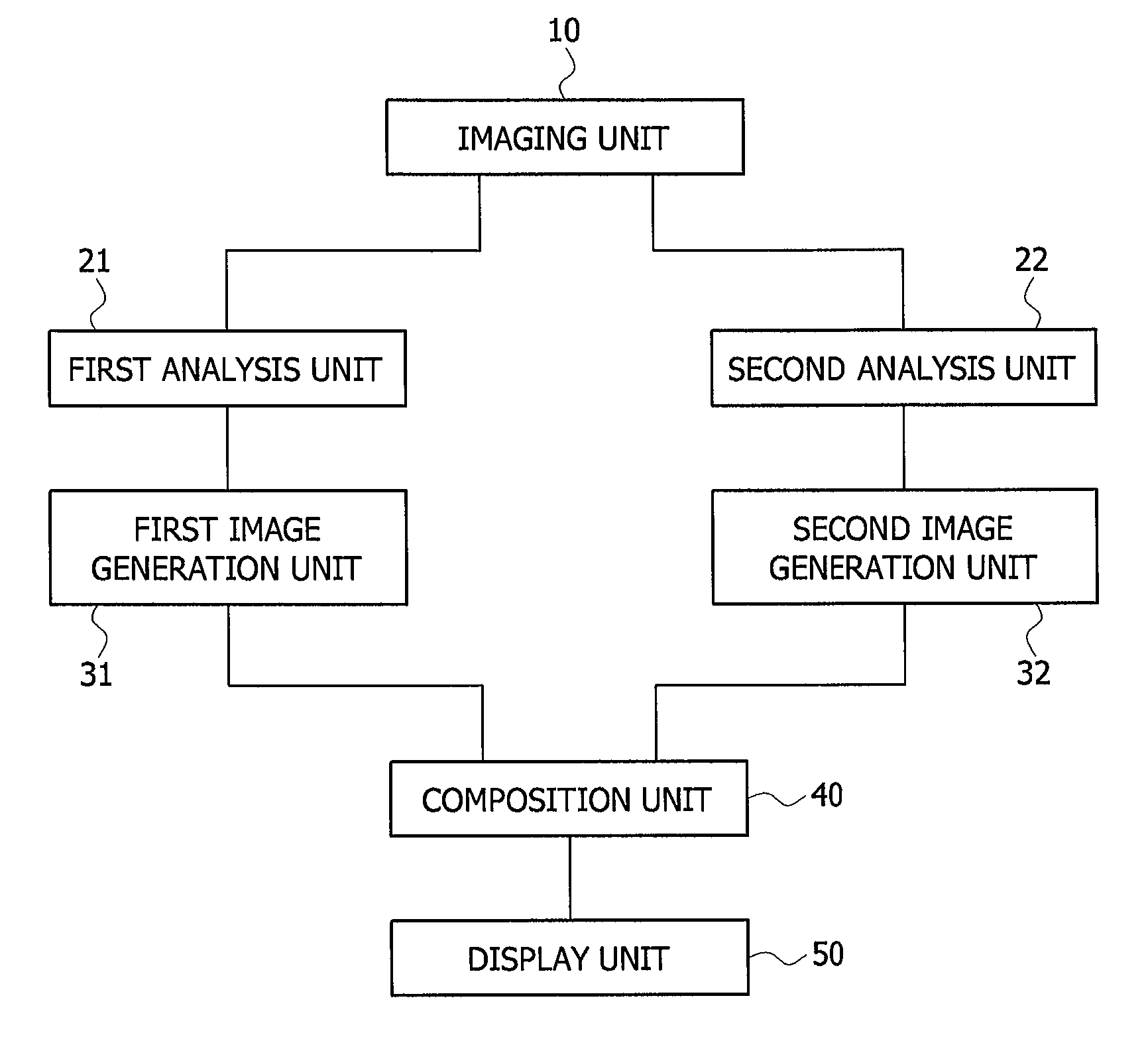
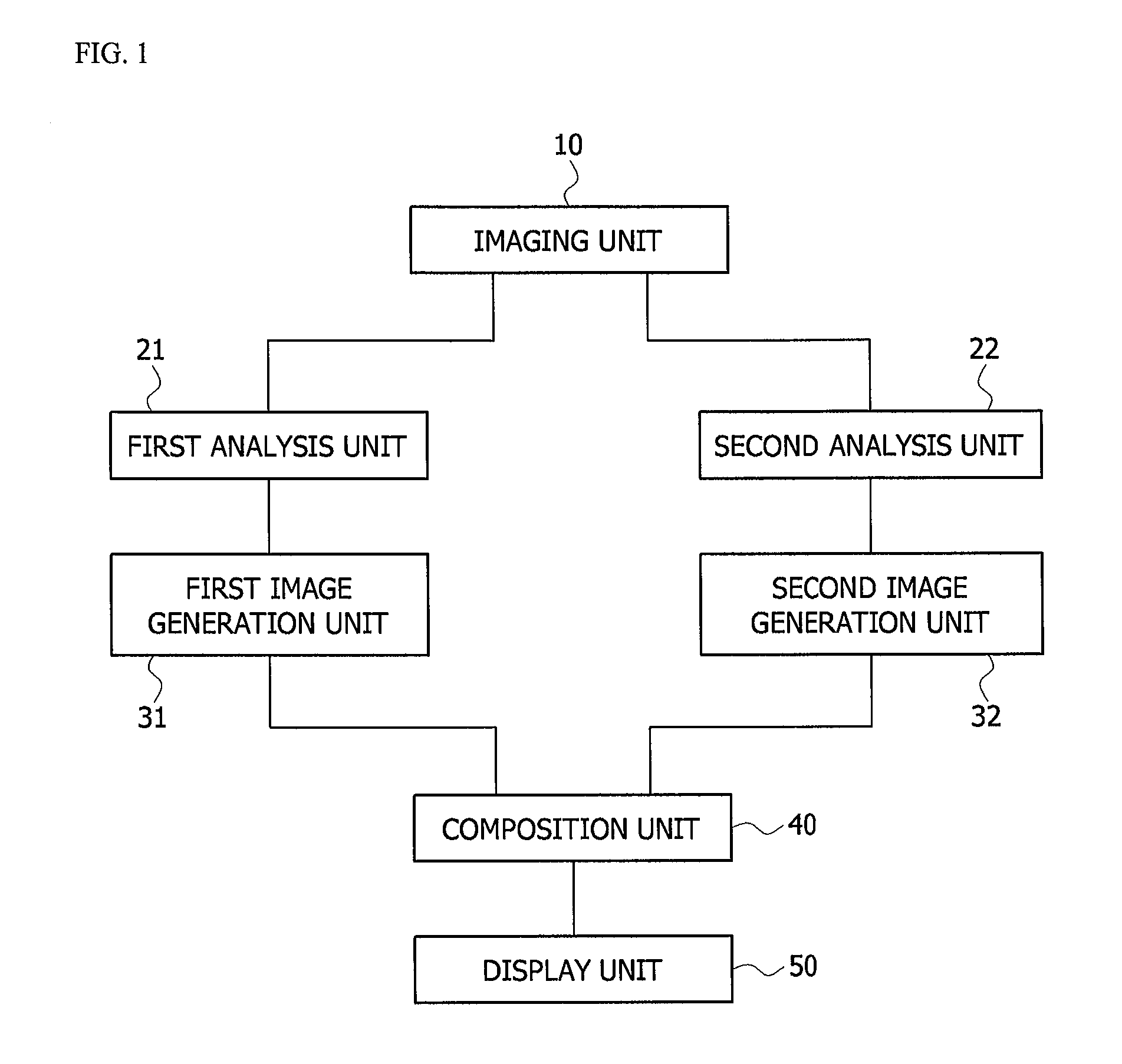
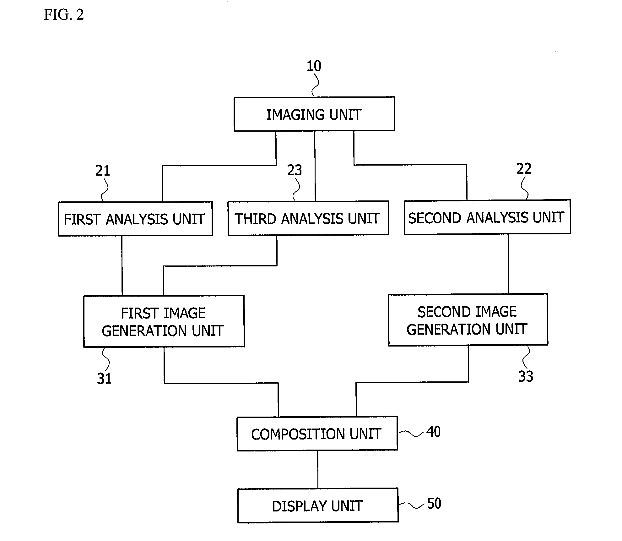
A system and method for providing an image capable of realizing conversion of a 3D tissue structure into which an implant is inserted into a 2D image using a contour technique are provided. The system for providing an image includes an imaging unit configured to photograph an inner part of a blood vessel into which an implant is inserted to provide a plurality of tomographic images, a first analysis unit configured to analyze the plurality of tomographic images to generate data on strut distribution of the stent, a second analysis unit configured to analyze the plurality of tomographic images to generate data on a thickness of a neointima, a first image generation unit configured to generate a strut distribution chart of a 2D image using the data on the strut distribution, a second image generation unit configured to generate a contour map for the thickness of the neointima using the data on the thickness of the neointima, and a composition unit configured to composite the strut distribution chart and the contour map.

Description

BACKGROUND[0001]1. Field of the Invention[0002]The present invention relates to a system and method for providing an image capable of generating an image providing information on an implant distributed in a tissue into which the implant is inserted and binding between the implant and the tissue.[0003]2. Discussion of Related Art[0004]Major causes of failure in implant placement are mainly divided into problems associated with implant materials caused during the implant placement, such as poor initial contact between a bone and a surface of an implant and peeling of a coated surface layer, and problems caused after the implant placement, such as an in vivo rejection response caused by reactive oxygen and various oxidants accumulated in osteocytes, stress, the onset of periimplantitis. This is because an implant and an osseous tissue surrounding the implant, both of which have different physical properties, are structurally brought into contact with each other to form an interface the...

Claims


Application Information

Patent Timeline
Patent Type & Authority Applications(United States)
IPC IPC(8): A61B5/00A61B6/00A61B8/08A61B19/00A61B6/03A61B5/107A61B8/12
CPCA61B5/4851A61B5/0066A61B5/1076A61B6/5223A61B8/12A61B2019/5257A61B6/032A61B8/0841A61B2019/5234A61B2019/5278A61B2019/524A61B19/5244A61B6/12A61B6/463A61B6/504
Inventor HONG, MYEONG KIKIM, BYEONG KEUKHA, JIN YONG
Owner IND ACADEMIC CORP FOUND YONSEI UNIV
Learn More