
Method and a device for determining an extrinsic information

a technology of extrinsic information and method, which is applied in the direction of digital transmission, electrical equipment, baseband systems, etc., can solve the problems of increasing the complexity of detection, affecting the detection of psk modulated symbols in real-time, and affecting the transmission efficiency to a considerable extent, so as to achieve the effect of simplifying the calculation of a single summand

Active Publication Date: 2014-10-02
ROHDE & SCHWARZ GMBH & CO KG
View PDF1 Cites 2 Cited by
  • Summary
  • Abstract
  • Description
  • Claims
  • Application Information

AI Technical Summary

Benefits of technology

The invention provides a method for determining extrinsic information in a transmission channel by approximating the probability density of the phase of the transmission channel. This method uses a logarithm to avoid a costly logarithtic sum and reduces the complexity of the calculations. The results show that the use of a log extrinsic information simplifies the determination of complex coefficients and reduces the cost compared to previous methods. This approach is efficient and can be implemented in real-time.

Problems solved by technology

If a transmission in short blocks is provided and if an estimation of the phase-transmission behavior is required in every block, a coherent detection of this kind impairs the transmission efficiency to a considerable extent and accordingly fails.
Instead, probability distributions of the phase of the transmission channel are additionally determined in the detection alongside estimated values for the individual transmitted PSK-modulated symbols, which leads to an increase in the complexity of the detection.
This detection method is disadvantageously characterized by a plurality of additions, multiplications and divisions, which impair the detection of PSK modulated symbols in real-time.
Moreover, this detection method is characterized by a wide dynamic range of the values to be calculated, which makes a fixed-point implementation more difficult.

Method used


Image

  • Method and a device for determining an extrinsic information
  • Method and a device for determining an extrinsic information
  • Method and a device for determining an extrinsic information

Examples


Embodiment Construction

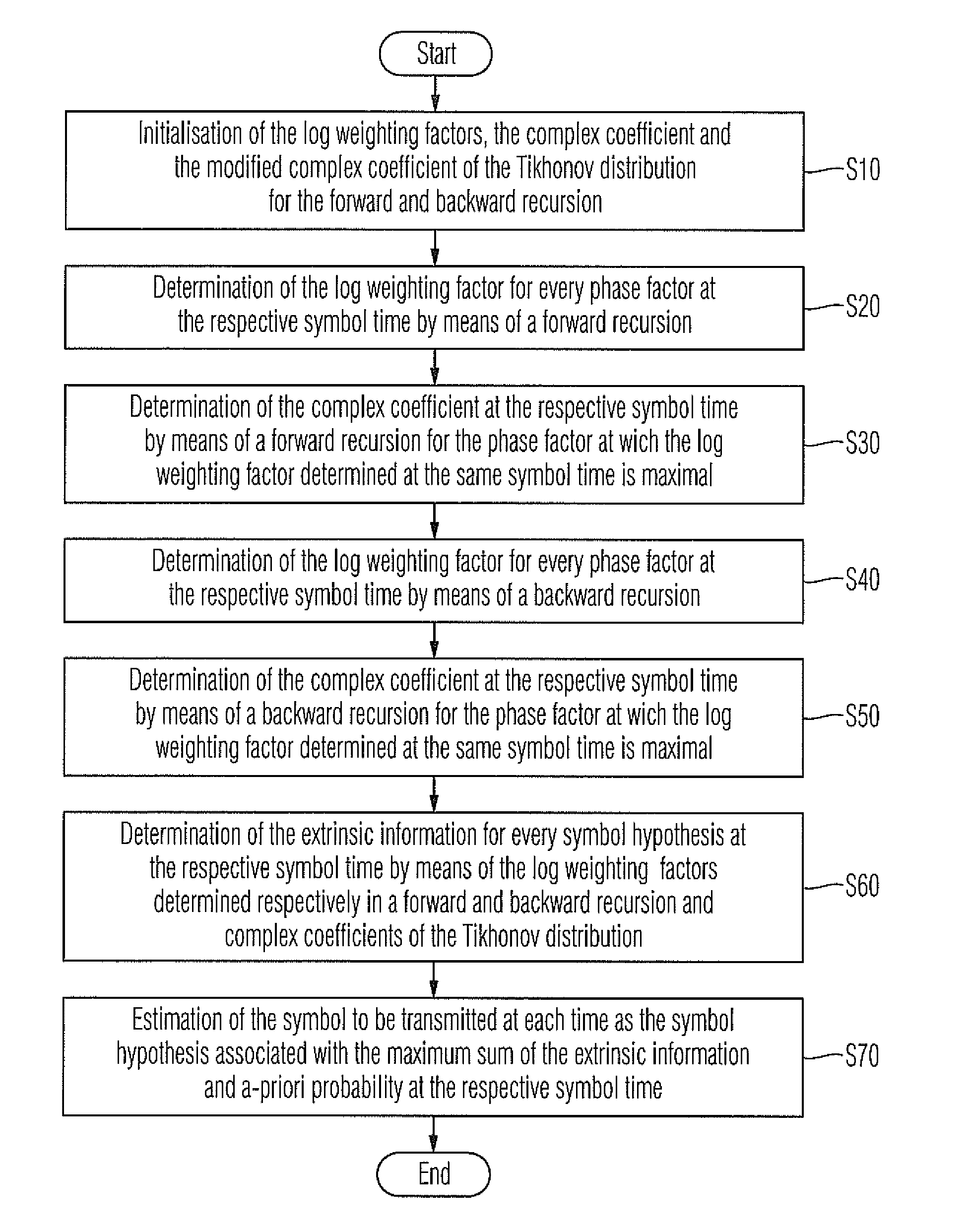
[0025]Before the method according to embodiments of the invention for determining an extrinsic information is described in greater detail with reference to the flow diagram in FIG. 1, and the device for determining an extrinsic information is described in greater detail with reference to the block-circuit diagram in FIG. 2, the mathematical basis required to understand the invention will be derived in the following section.

[0026]The following section considers a transmission system in which, at individual symbol times k=1, . . . , K, data symbols ak to be transmitted which satisfy the symbol alphabet of a multi-value Phase-Shift-Keying (PSK) according to equation (1), are subjected to a differential M-PSK modulation according to equation (2). The coded symbols ck generated in this manner at the individual symbol times k=1, . . . , K also satisfy the symbol alphabet of an M-PSK modulation according to equation (3).

ak∈{j2πMm,m=0,…,M-1}fork=1,…,K(1)ck=ck-1·ak(2)ck∈{j2πMm,m=0,…,M-1}fork...


PUM


Abstract

A device for detecting an estimated value for a symbol at a given time, which is supplied to a phase modulation and transmitted via a transmission channel with a time-variable phase, provides a unit for determining log weighting factors in a forward recursion, a unit for determining complex coefficients in a forward recursion, a unit for determining log weighting factors in a backward recursion, a unit for determining complex coefficients in a backward recursion, a unit for determining an extrinsic information, a unit for determining the phase factor with the maximal weighting factor in a forward recursion and a unit for determining the phase factor with the maximal weighting factor in a backward recursion.

Description

CROSS-REFERENCE TO RELATED APPLICATION[0001]The present application is a national phase application of PCT Application No. PCT / EP2012 / 053723, filed on Mar. 5, 2012, and claims priority to German Application No. 10 2011 006 565.2, filed on Mar. 31, 2011, and German Application No. 10 2011 078 565.5, filed on Jul. 4, 2011, the entire contents of which are herein incorporated by reference.BACKGROUND OF THE INVENTION[0002]1. Field of the Invention[0003]The invention relates to a method and a device for determining an extrinsic information.[0004]2. Discussion of the Background[0005]To allow an exact detection of Phase-Shift-Keying (PSK) modulated symbols in a transmission channel of which the phase transmission behavior is time-variable because of phase noise, pilot symbols are transmitted for an estimation of the transmission function of the transmission channel characterizing the time-variable phase-transmission behavior. If a transmission in short blocks is provided and if an estimati...

Claims


Application Information

Patent Timeline
Patent Type & Authority Applications(United States)
IPC IPC(8): H04L27/20
CPCH04L27/201H04L25/03171H04L25/067H04L27/2331
Inventor DETERT, THORBENVOLYANSKIY, MIKHAIL
Owner ROHDE & SCHWARZ GMBH & CO KG
Learn More