
I+hu 2 +l Average Current Mode (ACM) Control for Switching Power Converters

Active Publication Date: 2014-10-02
VIRGINIA TECH INTPROP INC
View PDF4 Cites 43 Cited by
  • Summary
  • Abstract
  • Description
  • Claims
  • Application Information

AI Technical Summary

Benefits of technology

The invention provides a power converter with average current mode control that has rapid transient response. It also provides an ACM control switching power converter that has good transient response and can operate in a discontinuous current mode (DCM).

Problems solved by technology

However, the decrease in inductor current causes a voltage across the inductor which drives the freewheel current and supplies additional current to the load.
This feedback circuit can be designed to provide very precise current control but the integration function of the feedback circuit results in slow transient response.
This feedback circuit can be designed to provide very precise current control but the low pass filter function and external ramp of the feedback circuit results in slow transient response.
It is well-known that ACM control, like any other constant frequency current mode control, can exhibit sub-harmonic instability and reduced dynamic response such that an external ramp is required to stabilize the current loop while the high-frequency pole reduces dynamic response.
However, such design is difficult since slopes of snc and sfc vary for several reasons including operation over a wide range of duty cycle such as in battery charger and power factor correction (PFC) applications and different input and output voltage combinations.
The limited bandwidth of compensator 30 can cause slope distortion of the Vcom waveform.
These are the possible causes of the loop instability issues of ACM control in practical power converter design and manufacture, integrated circuit controllers designed to be compatible with a wide range of inductor values and current sensor gains.
However, by doing so, stability is guaranteed at the cost of over-compensation which compromises dynamic performance, as shown in FIG. 3.
However, hysteretic current mode control can only control average current in a continuous conduction mode (CCM) and cannot function in a discontinuous conduction mode (DCM) and the switching frequency in this type of control is dependent on the actual value of the inductance which, as alluded to above, is subject to variation with temperature, DC current bias and manufacturing tolerances during operation (e.g. under variable load conditions).
These drawbacks, in turn, cause difficulty in synchronization with upstream, downstream or parallel connected converters or system clock and input and / or output filter design.
However, such added complexity also fails to provide for operation in a discontinuous conduction mode.
However, in such a case, the control circuit becomes even more complicated and light load efficiency is not improved.

Method used


Image

  • I+hu 2 +l Average Current Mode (ACM) Control for Switching Power Converters
  • I+hu 2 +l Average Current Mode (ACM) Control for Switching Power Converters
  • I+hu 2 +l Average Current Mode (ACM) Control for Switching Power Converters

Examples


Embodiment Construction

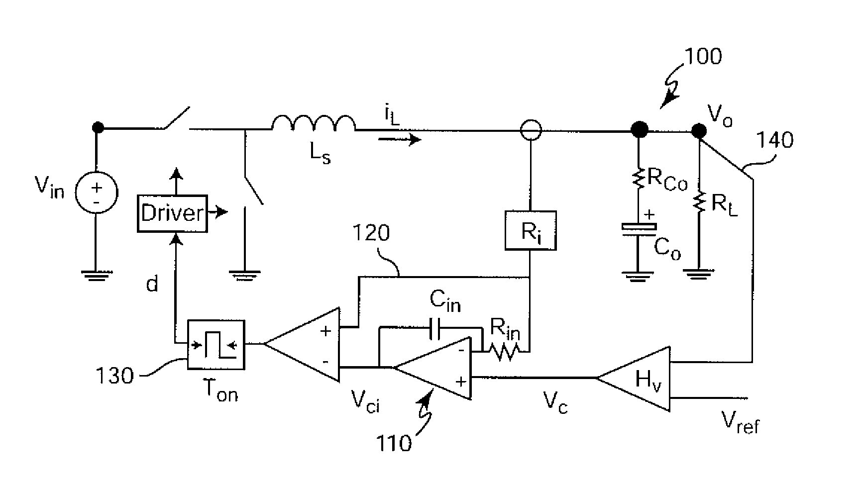
[0028]Referring now to the drawings, and more particularly to FIG. 1, there is schematically shown an application of average current mode (ACM) control to a buck converter 10. While buck converters and ACM control are known, FIGS. 1-3 are arranged to convey an understanding of the problems addressed by the invention and no part of FIGS. 1-3 is admitted to be prior art in regard to the invention. These Figures are therefore labeled “Related Art”. Further, while the invention will be described with reference to a buck converter which is chosen for the purpose in view of its familiarity and simplicity of constitution and operation, it is to be understood that the invention is applicable to any power converter topology and / or design.

[0029]As is well-known, the basic principle of buck converter operation is to alternately connect and disconnect an inductor and a power source with a switch Q1, also referred to as a top switch, causing current, iL, in the inductor, Ls, to increase. As indu...


PUM


Abstract

Providing a fast current sensor direct feedback path to a modulator for controlling switching of a switched power converter in addition to an integrating feedback path which monitors average current for control of a modulator provides fast dynamic response consistent with system stability and average current mode control. Feedback of output voltage for voltage regulation can be combined with current information in the integrating feedback path to limit bandwidth of the voltage feedback signal.

Description

CROSS-REFERENCE TO RELATED APPLICATIONS[0001]This application claims benefit of priority of U.S. Provisional Patent Application 61 / 806,545, filed Mar. 29, 2013, which is hereby incorporated by reference in its entirety.FIELD OF THE INVENTION[0002]The present invention generally relates to switching power converters and, more particularly to peak current mode (PCM) control and average current mode (ACM) control switching power converters.BACKGROUND OF THE INVENTION[0003]Virtually all electronic devices require some type of power converter to assure that electronic circuits therein receive power at the appropriate voltage even when there is wide variation in the current drawn by the load that such circuits constitute. Many commercially available integrated circuits adopt peak current mode (PCM) control to supply power to the switching circuits therein. However, peak current mode control only controls the peak current but cannot provide accurate average current control. Further, peak c...

Claims


Application Information

Patent Timeline
IPC IPC(8): H02M3/04H02M1/00
CPCH02M3/04G05F1/461G05F1/565H02M3/156H02M1/0009
Inventor YAN, YINGYILEE, FRED C.MATTAVELLI, PAOLO
Owner VIRGINIA TECH INTPROP INC
Learn More