Diagnostic Processing System, Onboard Terminal System, and Server

a processing system and terminal technology, applied in error detection/correction, testing/monitoring control systems, instruments, etc., can solve the problems of large processing load applied to an onboard terminal system, difficult to perform a detailed diagnosis, and large processing load

Inactive Publication Date: 2014-09-25
HITACHI CONSTR MASCH CO LTD
View PDF0 Cites 16 Cited by
  • Summary
  • Abstract
  • Description
  • Claims
  • Application Information

AI Technical Summary

Benefits of technology

The present invention provides a diagnostic processing system that can reduce the processing loads on an onboard terminal system and server. This means that the system can handle more data without overloading the system, making it more efficient and reliable.

Problems solved by technology

First, if an attempt is made to perform detailed diagnostic processing with a mounted diagnostic system, a problem arises in that a large processing load is applied to an onboard terminal system.
The performance of detailed diagnostic processing by a server's installed diagnostic system involves a similar problem that a large processing load is applied to the server.
Next, the mounted diagnostic system is accompanied by a practical problem in that compared with the server's installed diagnostic system, it is difficult to perform a detailed diagnosis because of the imposition of a restriction on the processing performance of the onboard terminal system.
Even if an abnormality is detected, sufficient information required for maintenance cannot hence be obtained, and as a consequence, a potential problem may arise in that sufficient lead time would hardly be assured for the avoidance of a machine stoppage.
When the working machine is performing work, for example, at a worksite where the communication status of radio communication channels is not good, the server cannot receive such sensor data without any fault, leading to a problem that no diagnostic processing can be performed.
Especially at a place with significant terrain changes such as a mine or the like, it is not easy to assure sufficient radio communication quality.

Method used


Image

  • Diagnostic Processing System, Onboard Terminal System, and Server
  • Diagnostic Processing System, Onboard Terminal System, and Server
  • Diagnostic Processing System, Onboard Terminal System, and Server

Examples


Embodiment Construction

[0049]With reference to the drawings, the present invention will hereinafter be described about an embodiment applied to a system for diagnosing an abnormalities of working machines used in a mine or the like, such as excavators and dump trucks. FIG. 1 is a schematic diagram showing the overall configuration of a diagnostic processing system according to the embodiment of the present invention.

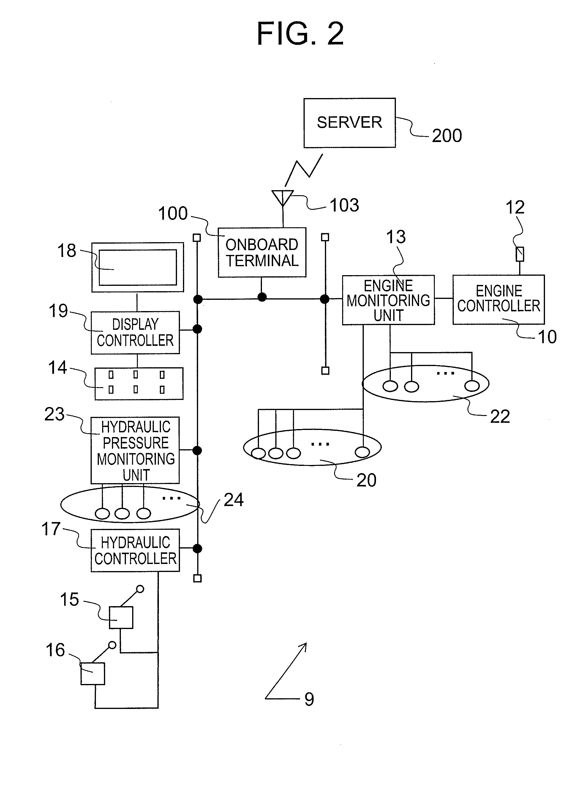
[0050]As shown in FIG. 1, in amine quarry, working machines (self-propelled machines) 1 such as excavators 1A and dump trucks 1B are used, and a diagnostic processing system 300 is employed to diagnose abnormalities of these working machines. In this diagnostic processing system 300, a server 200 is arranged at a control center 201 located near to or far from the quarry. Mounted on each working machine 1 are a position acquiring unit (now shown) for acquiring the position of the working machine itself by using GPS satellites 405, and various sensors (now shown). Onboard terminals (onboard term...


PUM


Abstract

Disclosed is a diagnostic processing system including an onboard terminal system and a server connected together via radio communication channels. The onboard terminal system is provided with a data receiving unit for receiving data from sensors arranged on a self-propelled machine and a first diagnostic unit for diagnosing an abnormality of the self-propelled machine, and the server is provided with a second diagnostic unit for diagnosing the abnormality of the self-propelled machine. The diagnostic processing system is configured such that one of the first diagnostic unit and second diagnostic unit performs a primary diagnosis as to the abnormality of the self-propelled machine based on the data received at the data receiving unit and transmits a result of the primary diagnosis to the other diagnostic unit, and upon receipt of the result of the primary diagnosis, the other diagnostic unit performs a secondary diagnosis based on the result of the primary diagnosis.

Description

CROSS-REFERENCE TO RELATED APPLICATION[0001]This application claims the priority of Japanese Patent Application 2013-62144 filed Mar. 25, 2013, which is incorporated herein by reference.BACKGROUND OF THE INVENTION[0002]1. Field of the Invention[0003]This invention relates to a diagnostic processing system for diagnosing an abnormality of a self-propelled machine, and also to an onboard terminal system and server useful in the diagnostic processing system.[0004]2. Description of the Related Art[0005]Working machines (self-propelled machines) useful in mines and the like, such as excavators and dump trucks, are operating all over the world for earth or stone excavation work, haulage work and so on, and in many instances, are required to perform continuous operation for improved productivity. If an unexpected failure occurs, it becomes necessary to stop the working machine for an inspection and for maintenance or a parts replacement so that the productivity is significantly lowered. To...

Claims


Application Information

Patent Timeline
IPC IPC(8): G05B9/02G06F11/07
CPCG06F11/0748G05B9/02G05B23/0262
Inventor FUJIWARA, JUNSUKESUZUKI, HIDEAKIUCHIDA, TAKAYUKIHIRUTA, TOMOAKI
Owner HITACHI CONSTR MASCH CO LTD
Why Eureka
Try Eureka