Method and system for tms dose assessment and seizure detection

a dose assessment and seizure detection technology, applied in the field of tms dose assessment and seizure detection, can solve the problems of depolarization or hyperpolarization in the brain neurons, high frequency patterns carry a risk of elevated seizure risk, and the effectiveness of treatment is missing

Inactive Publication Date: 2014-09-18
NEXSTIM
View PDF8 Cites 19 Cited by
  • Summary
  • Abstract
  • Description
  • Claims
  • Application Information

AI Technical Summary

Benefits of technology

[0021]In an embodiment, the seizure monitoring module is in communication with the control means, so that in the event of a seizure being detected or predicted, the control means can stop the operation of the TMS device.

Problems solved by technology

In particular, TMS causes depolarization or hyperpolarization in the neurons of the brain.
However, high frequency patterns carry a risk of elevated seizure risk.
However, online feedback for the effectiveness of the treatment is missing, and this protocol is unable to detect a seizure in time.
However, applying an EEG measurement after the TMS treatment session could prolong the entire treatment session significantly.
However, monitoring a patient's EEG during a TMS pulse presents technical problems, since TMS-compatible EEG systems can generally not accommodate TMS measurements because the high-energy dynamic magnetic fields generated by the TMS device induces undesirable voltages in the EEG leads, thereby making the use of conventional EEG hardware unsuitable for the safe and effective monitoring of TMS therapy.
Typical preamplifiers used in EEG systems take a relatively long time to recover after being saturated by a TMS pulse.
Additional gating and sampling circuitry is undesirable because it requires additional circuitry and because it can be complicated.
An additional complication that occurs when a patient's EEG is monitored during TMS occurs because of the use of metal electrodes to sense EEG signals.
Large eddy currents induced by the TMS pulse or pulses in the metal electrodes can cause localized heating that may result in burns to a patient's scalp.
This presents a safety hazard.

Method used


Image

  • Method and system for tms dose assessment and seizure detection
  • Method and system for tms dose assessment and seizure detection
  • Method and system for tms dose assessment and seizure detection

Examples


Embodiment Construction

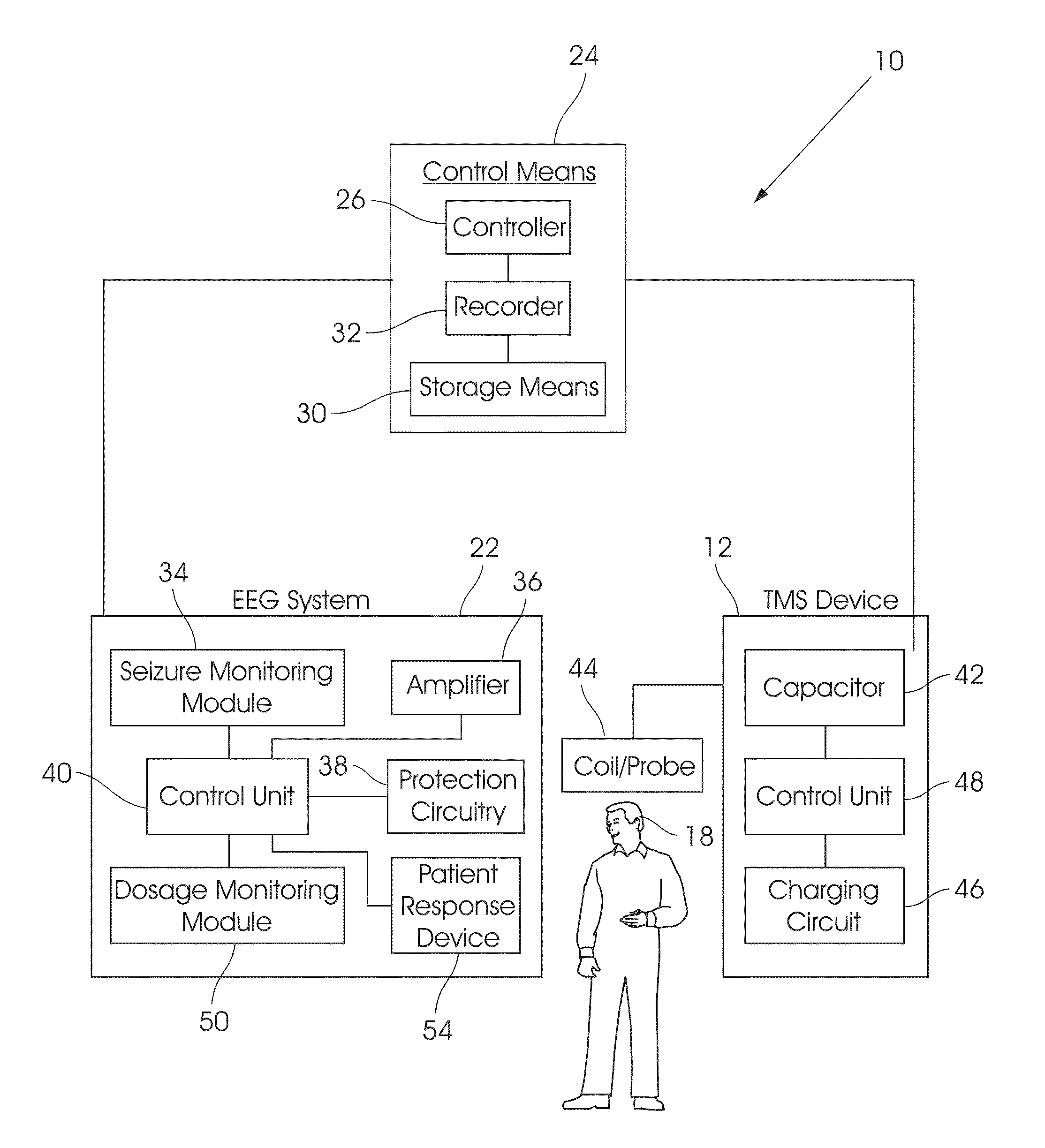
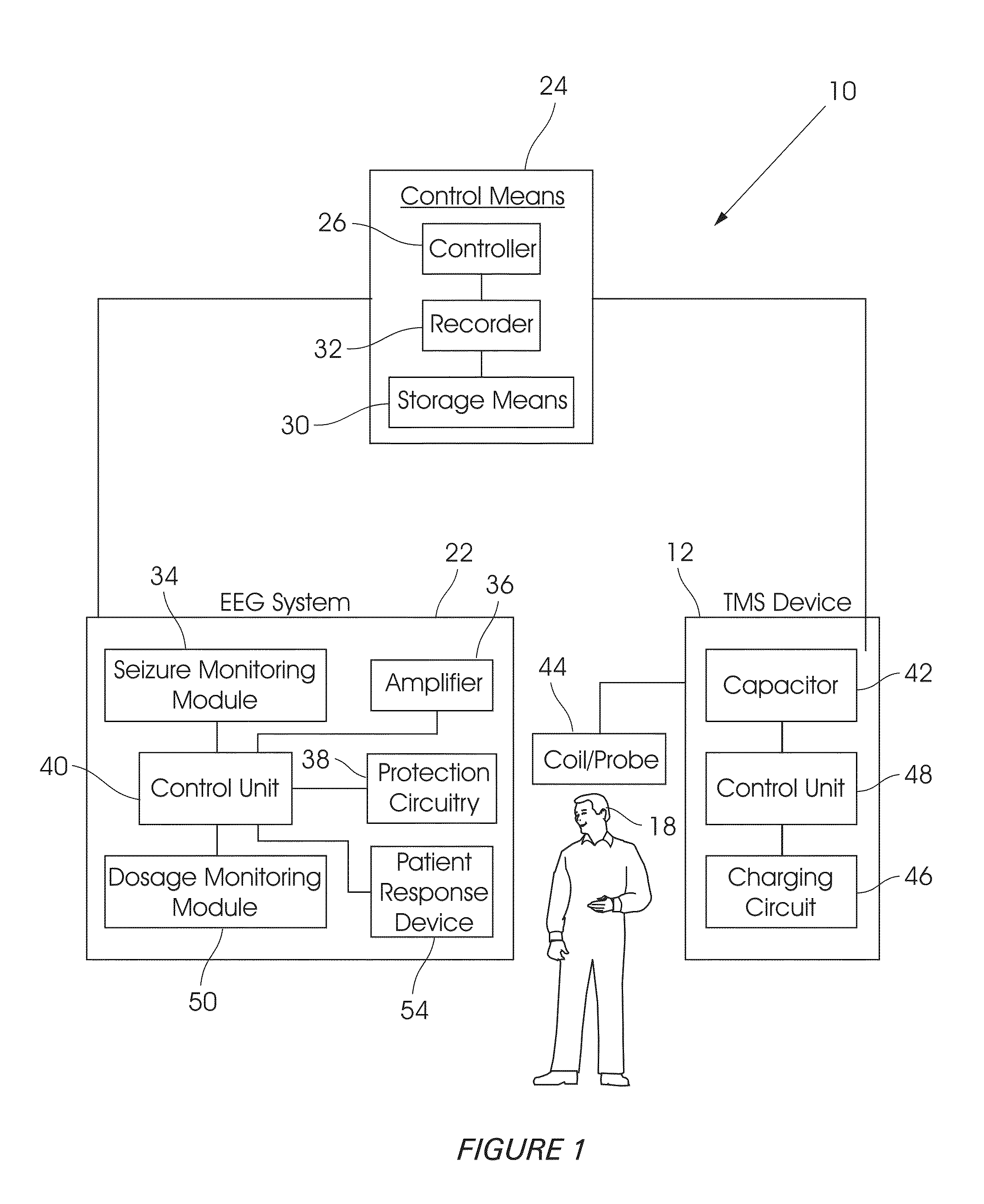
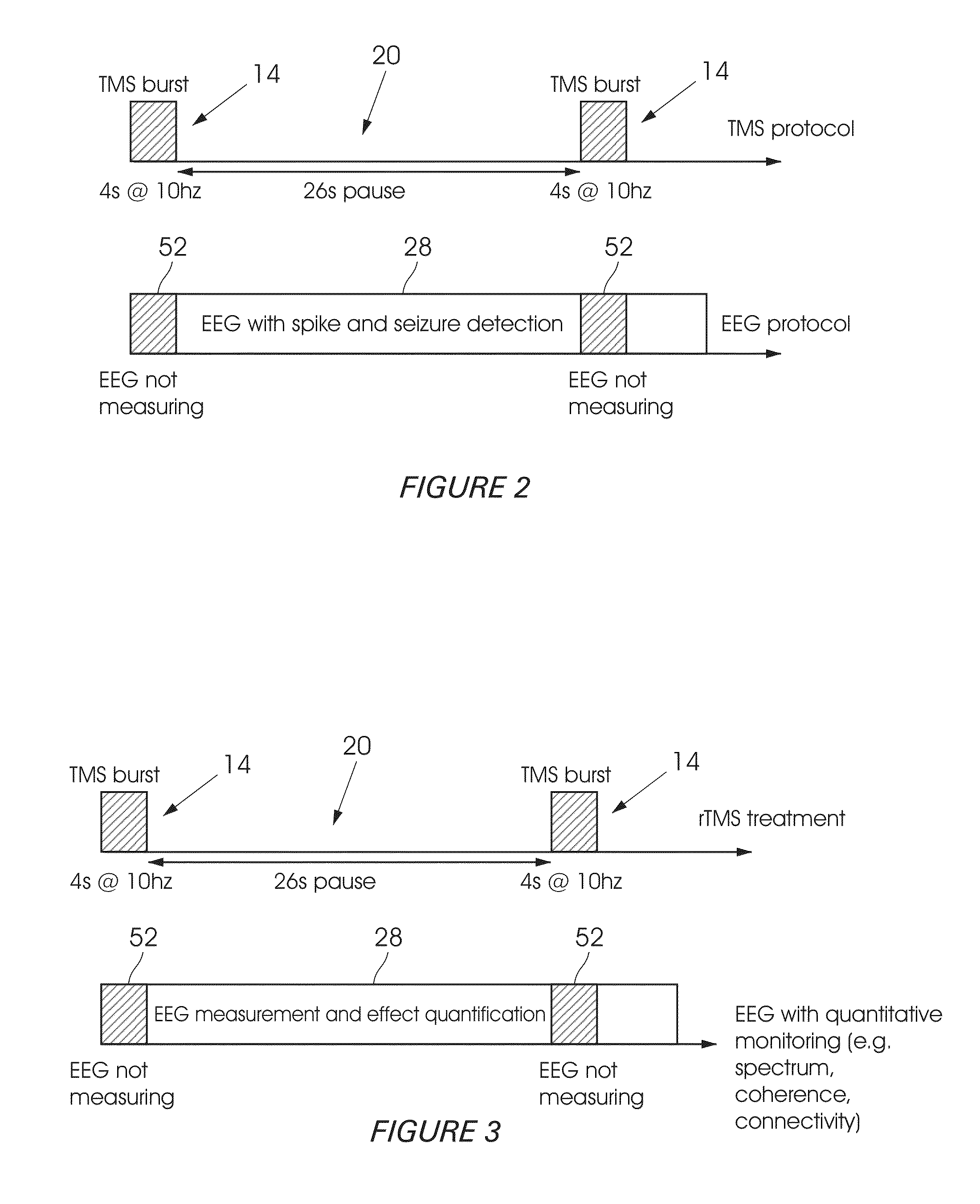
[0057]Referring first to FIGS. 1 to 4, a system 10 for monitoring a patient's EEG (electroencephalogram) during TMS (Transcranial Magnetic Stimulation) is shown. The system 10 comprises a TMS device 12 to generate, when in active state, a plurality of magnetic pulses. The pulses can be applied either as a burst, comprising a plurality of pulses grouped together, as indicated by arrow 14 in FIGS. 2 to 4, or as individual pulses, as indicated by arrows 16 in FIG. 4, to the patient's head 18 in accordance with a TMS treatment protocol.

[0058]Based on established safety guidelines, TMS treatment protocols often combine active stimulation (corresponding to arrows 14 in FIGS. 2 to 4) with long pauses in between (as indicated by arrows 20) in FIGS. 2 to 4. The duration of these pauses often exceeds the duration of active stimulation, as clearly shown. The waiting periods defined by the pauses are to be used for measuring diagnostic data that could be interpreted in real-time and used for gu...


PUM


Abstract

A method of and system for monitoring a patient's EEG (electroencephalogram) during TMS (Transcranial Magnetic Stimulation) are disclosed. The system comprises a TMS device to generate, when in an active state, a plurality of magnetic pulses, which can be applied either as a burst, comprising a plurality of pulses grouped together, or as individual pulses, to the patient's head, in accordance with a TMS treatment protocol. An EEG system is provided to measure EEG data resulting from the TMS treatment protocol being applied to the patient. The system further comprises control means in communication with the TMD device and the EEG system, the control means being arranged to activate the EEG system during the time periods when the TMS device is not generating pulses, such that the EEG data measurement is continuously applied or interleaved with the magnetic pulses being generated in accordance with the TMS treatment protocol, so as to monitor treatment efficacy and detect potential seizures.

Description

FIELD OF THE INVENTION[0001]This invention relates to a method and device for TMS dose assessment and seizure detection.BACKGROUND TO THE INVENTION[0002]Transcranial magnetic stimulation (TMS) is a technique for stimulating the human brain noninvasively. In particular, TMS causes depolarization or hyperpolarization in the neurons of the brain. TMS uses electromagnetic induction to induce weak electric currents using a rapidly changing magnetic field; this can cause activity in specific or general parts of the brain with minimal discomfort, allowing the functioning and interconnections of the brain to be studied. TMS thus uses the principle of inductance to get electrical energy across the scalp and skull without the pain of direct percutaneous electrical stimulation. It involves placing a coil of wire on the scalp and passing a powerful and rapidly changing current through it. This produces a magnetic field which passes unimpeded and relatively painlessly through the tissues of the ...

Claims


Application Information

Patent Timeline
Patent Type & Authority Applications(United States)
IPC IPC(8): A61B5/0484A61B5/00
CPCA61B5/4094A61B5/0484A61B5/4836A61N2/006A61N2/02A61B5/369A61B5/377
Inventor NEUVONEN, TUOMAS
Owner NEXSTIM
Why Eureka
Try Eureka