
Image Generation

a technology of image and video card, applied in the field of image generation, can solve the problems of difficult physical correct addition of video card to the computer, high cost of solution, and inconvenient for many non-technical users of computers, and achieve the effect of effective solution

Active Publication Date: 2014-09-18
DISPLAYLINK (UK) LTD
View PDF2 Cites 4 Cited by
  • Summary
  • Abstract
  • Description
  • Claims
  • Application Information

AI Technical Summary

Benefits of technology

The patent describes an invention that allows for video to be transmitted over limited networks, such as USB, with a quality that is not obviously different from standard methods. The invention uses a compression technique called the Haar transform, which is fast and effective for computer screens, while also maintaining sharp edges when showing photographic information. The decoding method is also efficient, making it suitable for low-latency encoding and decoding. Overall, the invention allows for effective video transmission and display capabilities with low-cost networks.

Problems solved by technology

The connection of an additional display device to a computer presents a number of problems.
However, this solution is relatively expensive and is not suitable for many non-technical users of computers, for whom physically correctly adding the additional video card to their computer is a difficult task.
This means that when connecting an additional display device using a limited bandwidth technology such as USB, certain complex tasks can be difficult to achieve.

Method used


Image

  • Image Generation
  • Image Generation
  • Image Generation

Examples


Embodiment Construction

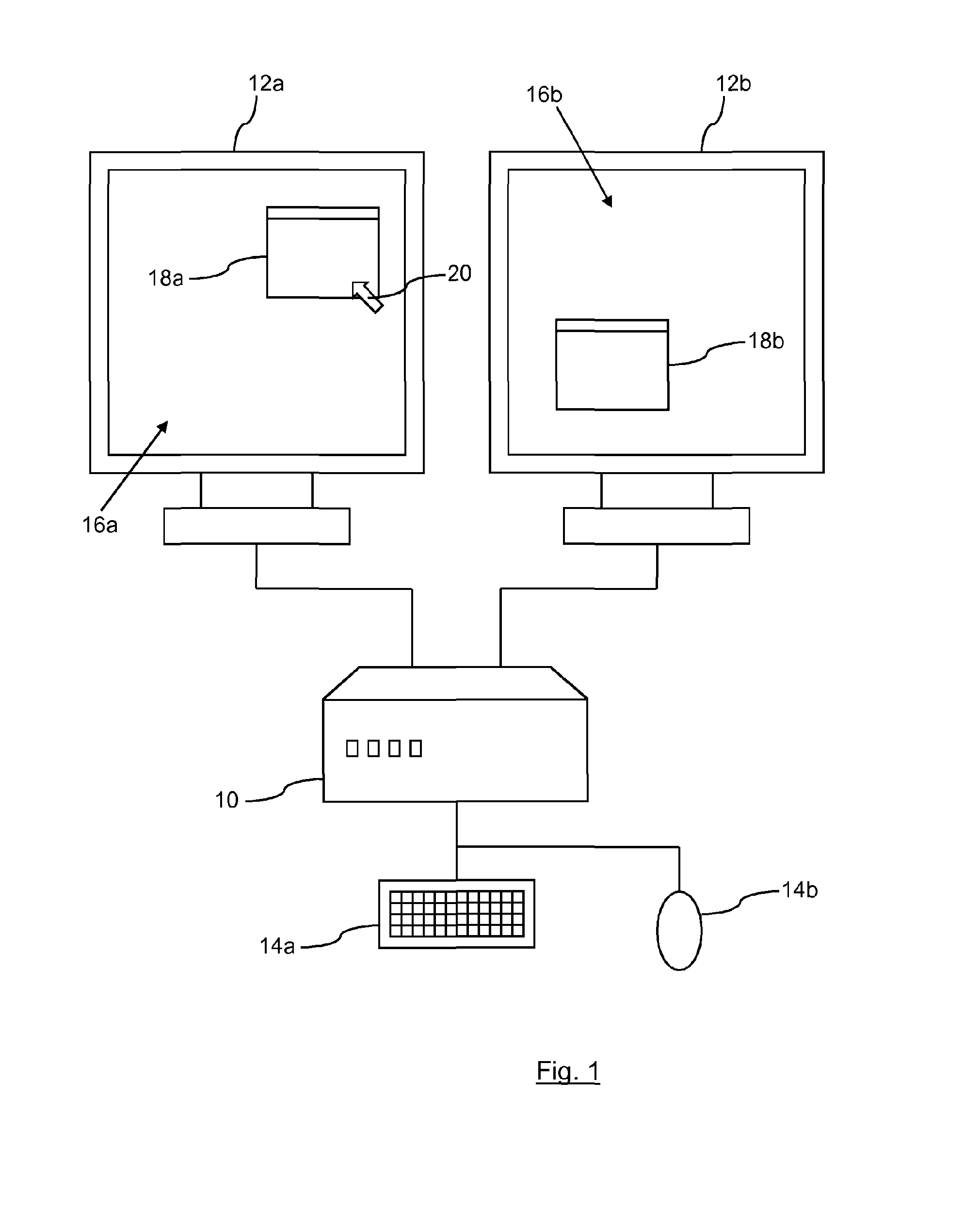
[0024]A display system is shown in FIG. 1. The system comprises a processing device 10, display devices 12 and user interface devices 14. The user interface devices are a keyboard 14a and a mouse 14b. The system shown in FIG. 1 is a standard desktop computer, with an additional display device 12b, which is composed of discrete components that are locally located but could equally be a device such as a laptop computer or suitably enabled handheld device such as a mobile phone or pda (personal digital assistant) all using an additional display 12b. Similarly, the system may comprise part of a networked or mainframe computing system, in which case the processing device 10 may be located remotely from the user input devices 14 and the display devices 12, or indeed may have its function distributed amongst separate devices.

[0025]The display devices 12 show images 16, and the display of the images 16 is controlled by the processing device 10. One or more applications are running on the pr...


PUM


Abstract

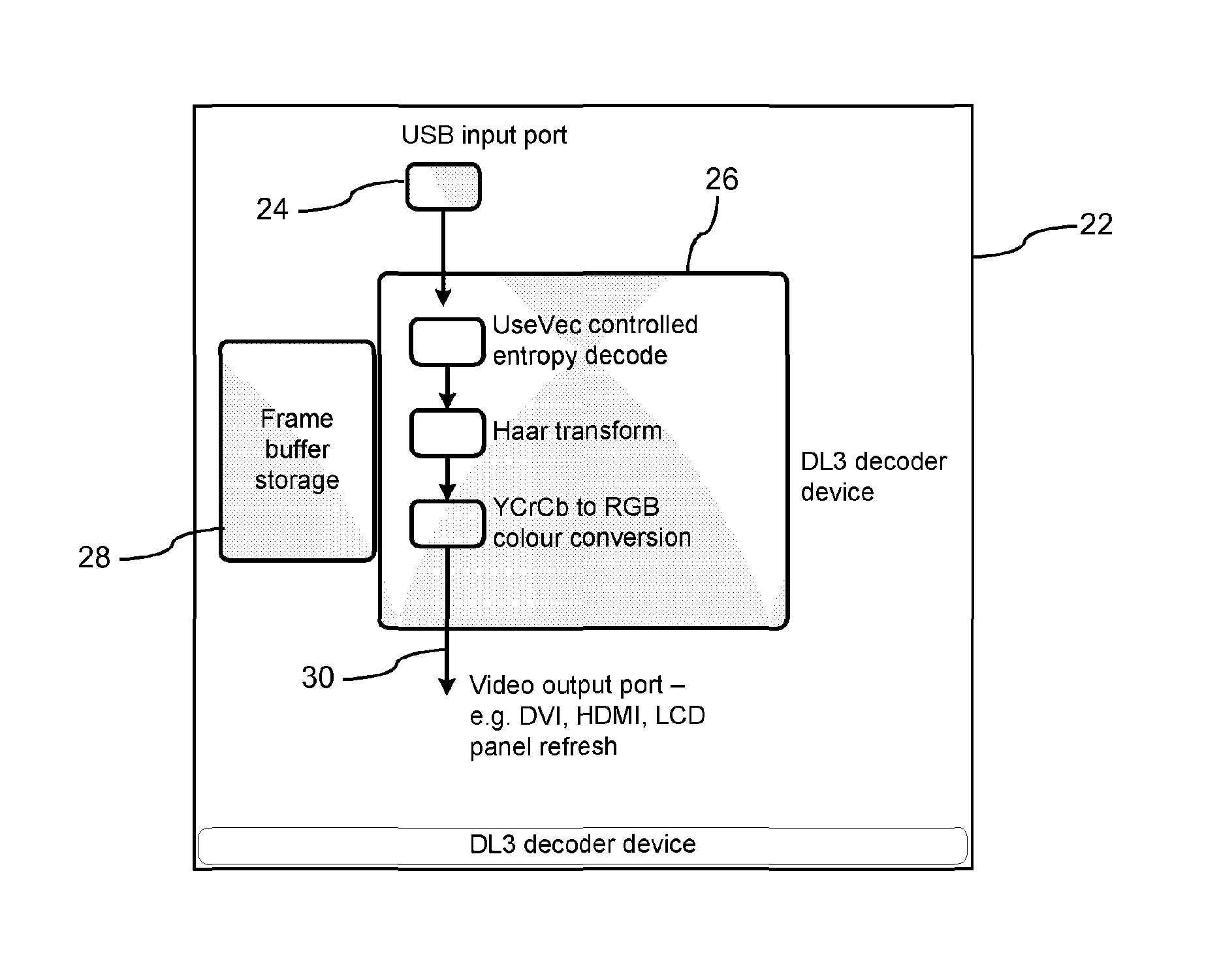
A method of generating an image comprises receiving a signal over a USB interface comprising encoded display data for one or more rectangular group of pixel tiles within an image and position data for the or each group of pixel tiles. The coefficients are obtained from the encoded display data, maybe by converting variable bit length fields into AC coefficients and an inverse Haar transform performed on them to generate pixel data for each rectangular group of pixel tiles. A frame buffer, which may be part of the display, is then updated with the generated pixel data ready for output to the display device. Copy protection may also be incorporated using AES negotiated over HDPC.

Description

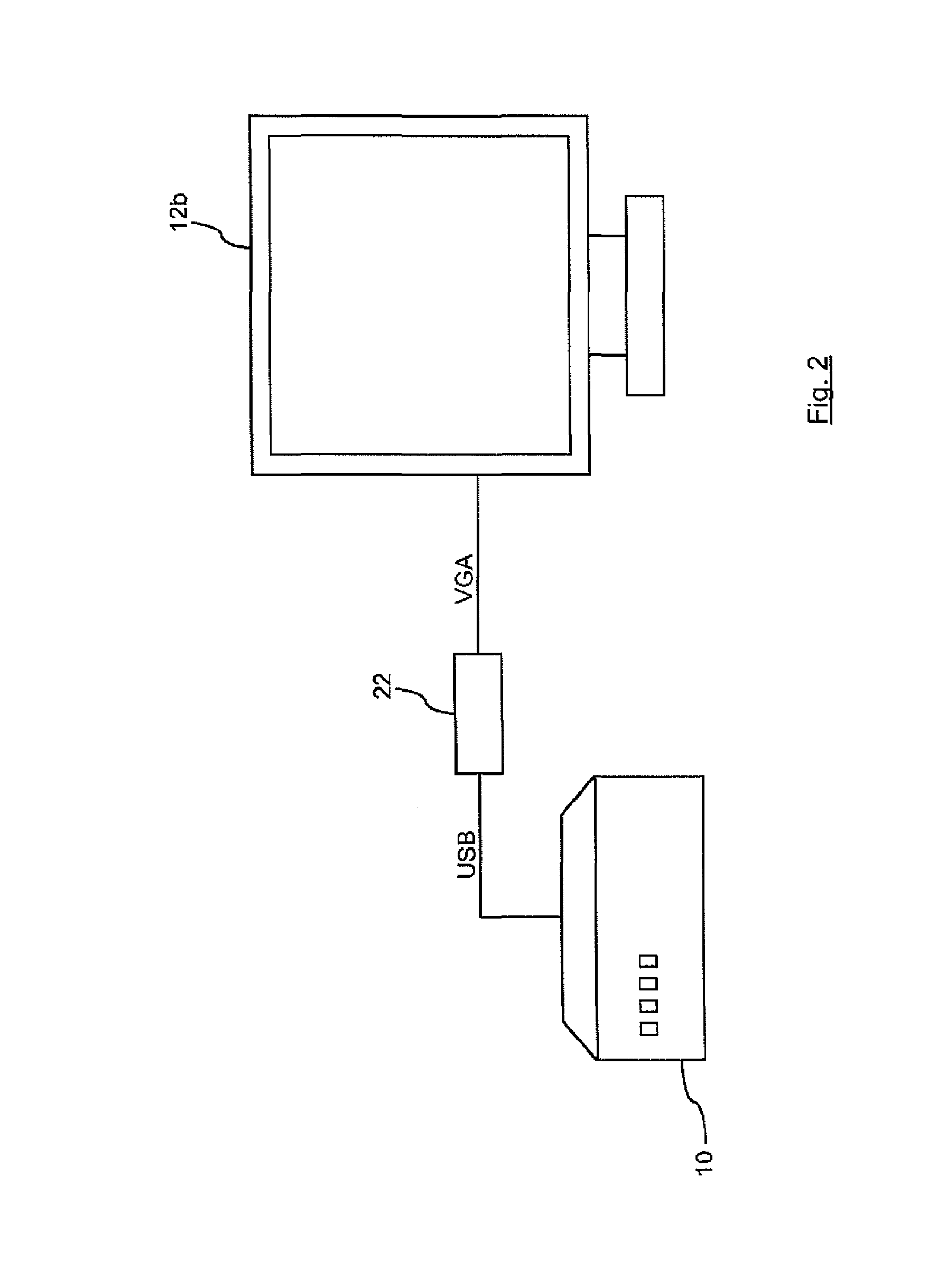
BACKGROUND OF THE INVENTION[0001]This invention relates to a method of generating an image and to a device for generating an image.[0002]In desktop computing, it is now common to use more than one display device. Traditionally, a user would have a computer with a single display device attached, but now it is possible to have more than one display device attached to the computer, which increases the usable display area for the worker. For example, International Patent Application Publication WO 2007 / 020408 discloses a display system which comprises a plurality of display devices, each displaying respectively an image, a data processing device connected to each display device and controlling the image displayed by each display device, and a user interface device connected to the data processing device. Connecting multiple display devices to a computer is a proven method for improving productivity.[0003]The connection of an additional display device to a computer presents a number of p...

Claims


Application Information

Patent Timeline
Patent Type & Authority Applications(United States)
IPC IPC(8): G09G5/395
CPCG09G5/395G06F3/1415G09G2340/02H04N21/4122H04N21/43632G06F3/1423G06T1/60G09G5/006G09G2370/12
Inventor STOYE, WILLIAM
Owner DISPLAYLINK (UK) LTD
Learn More