Structure of transformer's iron core

a transformer and iron core technology, applied in the direction of transformer/inductance details, basic electric elements, electrical equipment, etc., can solve the problems of affecting the overall transferring efficiency of the power source, affecting and the structure with relatively high magnetic leakage is unable to meet the user's requirement of low magnetic leakage. to achieve the effect of improving the competitiveness of the market and ameliorating at least some disadvantages

Inactive Publication Date: 2014-09-18
YUJING TECH CO LTD
View PDF4 Cites 4 Cited by
  • Summary
  • Abstract
  • Description
  • Claims
  • Application Information

AI Technical Summary

Benefits of technology

[0014]In light of the above-mentioned disadvantages of the prior art, the invention provides an improved structure of transformer's iron core that is capable of overcoming the shortcomings of the prior art, satisfying the requirements of the industry, as well as improving the competitiveness in the market. It aims to ameliorate at least some of the disadvantages of the prior art or to provide a useful alternative.

Problems solved by technology

As a result, besides being relatively smaller in magnetic flux area, due to the increase of the transverse magnetic flux length that results in increase of magnetic reluctance and magnetic leakage, and consequently affecting the overall transferring efficiency of power source.
Although Eddy current loss can be lower in a small content by employing multiple layers of stacked-up metal strips (6), the thickness of the metal strip (6) still needs to be rigorously controlled making the assembling work difficult and the cost higher.
1. The structure having relatively high magnetic leakage is unable to satisfy the user's requirement of having low magnetic leakage since each of the metal strips (6) and the main core parts (71) of the iron core (7) appear extended in perpendicular direction;
2. Since the pole legs (63) stretching out through the iron core (7) of the metal strips (6) appear extended in perpendicular direction with the main core part (71), therefore, after being assembled with the circuit board, the structure having the main core part (71) of iron core (7) appears extended in parallel direction with the circuit board is unable to satisfy the requirement of the specification having the main core part (71) of iron core (7) appears extended in perpendicular direction with the circuit board;
3. The recesses (74) furnished on the side of the side parts (72) of the iron core (7) for each of the wire connecting seats (54) to be outwardly connected to each of the polar legs (63). However, this kind of design sometimes is unable to satisfy the requirements for the transformer's specification having a multiple sets of wire drawing head since the iron core has at most four recesses (74) only.

Method used


Image

  • Structure of transformer's iron core
  • Structure of transformer's iron core
  • Structure of transformer's iron core

Examples


Embodiment Construction

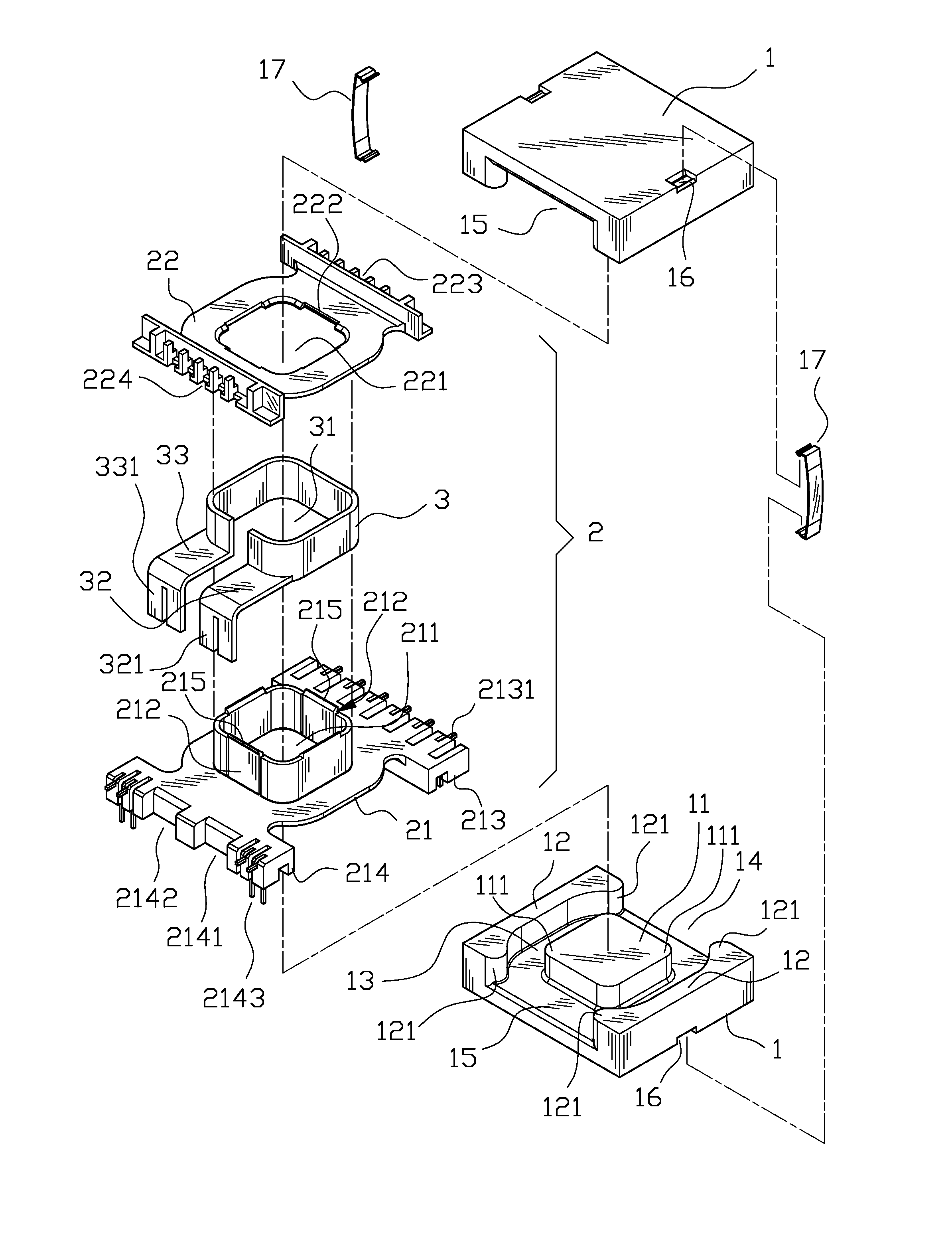
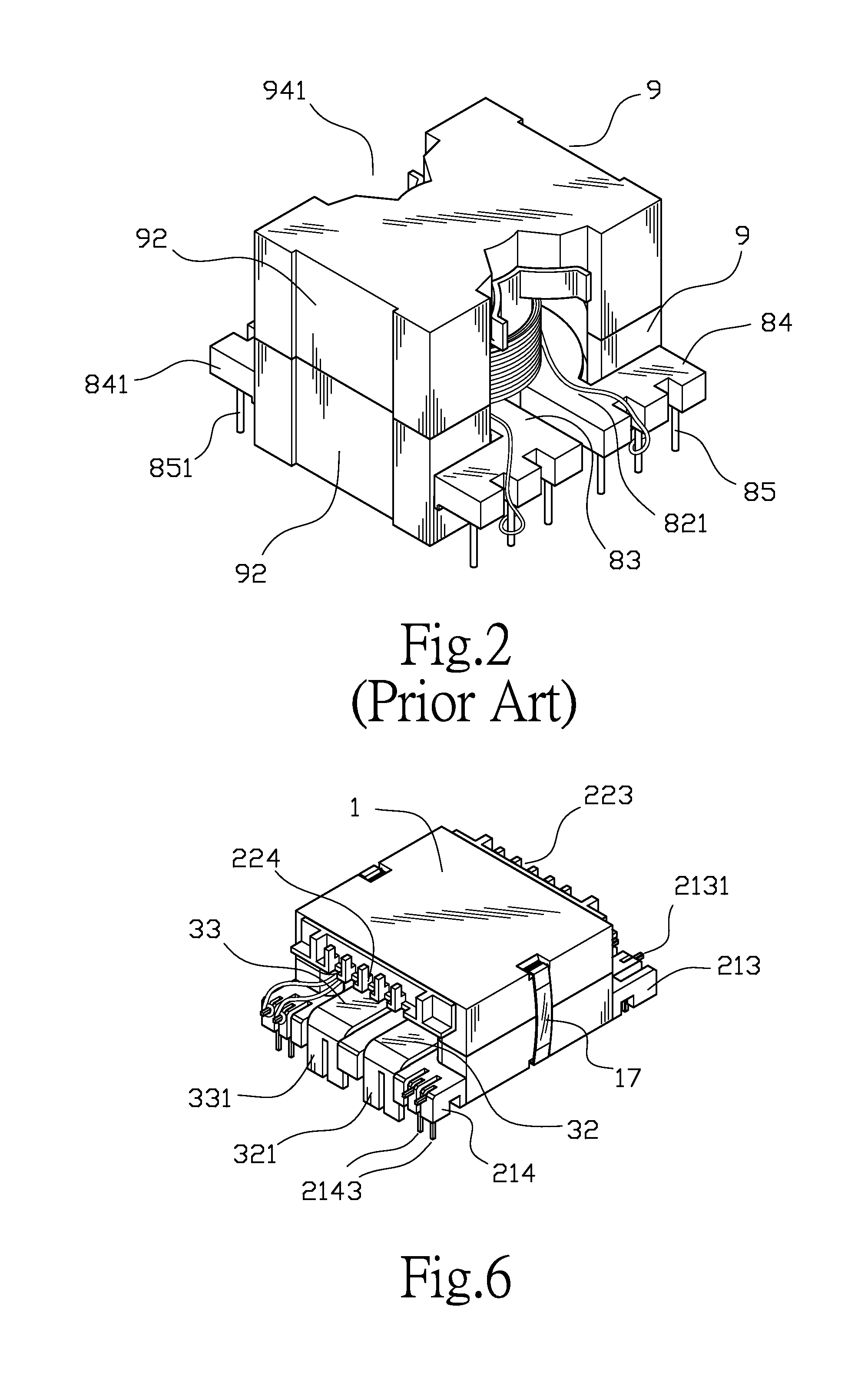
[0029]FIG. 5 is an isometric exploded view of the structure of the transformer and its related embodied parts of the invention and FIG. 6 is an isometric view of the assembled structure of the transformer and its related embodied parts of the invention. As shown in FIG. 5 and FIG. 6, the improved structure of transformer's iron core of the invention mainly includes two iron cores (I) each having a salient main core part (11) furnished at the center part thereof. The main core part (11) being a structure having a rectangular or rectangular horizontal cross-section has a pair of oppositely configured side wing parts (12) furnished at the outside thereof. A containing circumferential channel (13) formed between the main core part (11) and the side wing parts (12) has a pair of oppositely configured side openings (14), (15) making the containing circumferential channel (13) form communicative exits toward the outside through the two side openings (14), (15). Moreover, the pair of side o...


PUM

PropertyMeasurementUnit
structureaaaaaaaaaa
widthaaaaaaaaaa
magnetic fluxaaaaaaaaaa

Abstract

An improved structure of transformer's iron core mainly has an iron core main body, having a salient main core part with a rectangular horizontal cross-section, furnished at the center part thereof. The main core part has a pair of oppositely configured side wing parts furnished at the outside thereof. A containing circumferential channel formed between the main core part and the side wing parts has a pair of oppositely configured side openings making the containing circumferential channel form communicative exits toward the outside through the two side openings. By employing the salient main core part with a rectangular-shaped horizontal cross-section, the invention is capable of forming longer outer circumference to effectively increase the area of the magnetic flux thereof under the premise of same bobbin. Moreover, in association with the relatively larger side openings that are capable of providing lead frame containing in the containing ring-trench to be outwardly connected to a relatively wider wire connecting seats, the invention is capable of satisfying the required specification of multiple wire-drawing.

Description

BACKGROUND OF THE INVENTION[0001]1. Field of the Invention[0002]The invention relates to an improved structure of transformer's iron core, and more particularly, to an improved structure of transformer's iron core having both relatively larger side-opening and relatively larger magnetic flux area generated between each of the windings.[0003]2. Description of the Prior Art[0004]FIG. 1 is an isometric exploded view of the structure of the transformer of the prior art while FIG. 2 is an isometric view of the assembled structure of the transformer of the prior art. As shown in FIG. 1 and FIG. 2, the most widespread application of transformer's iron core and its related components mainly include a lead frame (8), two iron cores (9) having one of them at the top while the other one of them at the bottom, and coil (821). The lead frame (8) has a central hole (81) furnished at the center thereof. A bobbin (82) provided, to be wound by a coil (821) which includes a primary winding, a seconda...

Claims


Application Information

Patent Timeline
Patent Type & Authority Applications(United States)
IPC IPC(8): H01F3/08
CPCH01F3/08H01F27/263H01F27/306
Inventor YANG, SEN-TAI
Owner YUJING TECH CO LTD
Why Eureka
Try Eureka