
Charging an input capacitor of a load control device

a load control device and input capacitor technology, applied in the direction of electric variable regulation, process and machine control, instruments, etc., can solve the problems of inability to connect the neutral side of the ac power source to the wallbox where the mechanical switch is located, the cost of running additional wiring is high, and the need for subsequent repair

Active Publication Date: 2014-09-18
LUTRON TECH CO LLC
View PDF6 Cites 89 Cited by
  • Summary
  • Abstract
  • Description
  • Claims
  • Application Information

AI Technical Summary

Benefits of technology

This patent describes a load control device that can control the amount of power delivered to an electrical load. The device includes a power converter and an input capacitor that works together to control the bus voltage. This bus voltage is then used to charge a supply capacitor, which in turn powers the load. The device can operate in different modes, such as boost or buck, to efficiently control power delivery. The feedback circuit provides a signal to the control circuit, which helps to regulate the voltage and ensure a stable power output. The technical effects of this patent are to provide a more efficient and precise means for controlling power delivery to electrical loads.

Problems solved by technology

Moreover, a neutral wire connection coupled to the neutral side of the AC power source may not be available in the wallbox where the mechanical switch is located.
Running additional wiring can be very expensive, due to the cost of the additional electrical wiring as well as the cost of installation.
In addition, if the pre-existing wiring from the mechanical switch to the ballast runs behind a fixed ceiling or wall (e.g., one comprising plaster or expensive hardwood), the electrician may need to breach the ceiling or wall to install the new electrical wiring, which will thus require subsequent repair.
A further complication may arise when the existing ceiling contains asbestos.
The process is expensive and time consuming.
Therefore, the prior art three-wire dimming ballast does not work well in retrofit installations as described above because the ballast requires two electrical connections—not one—between the dimmer switch and the ballast (i.e., the switched-hot voltage and the dimmed-hot voltage) and the dimmer switch requires connection to a neutral wire coupled to the neutral side of the AC power source in addition to the hot wire.
However, the dimmer switch is only able to control the two-wire dimming ballasts in unison since each ballast receives the identical phase-control voltage from the dimmer switch.
The dimmer switch cannot individually control the intensities of each of the ballasts coupled to the dimmer switch.
The prior art digital dimming ballasts require that the wired digital communication link is coupled to each of the ballasts—in addition to the power wiring—and thus are not well suited to retrofit installations, where the digital dimming ballasts are replacing non-dimming ballasts.
However, such power-line carrier communication systems have many disadvantages that have prevented the systems from enjoying wide commercial success.
Typically, the control devices of power-line carrier communication systems require connections to both the hot side and the neutral side of the AC power source, which connections may not both be available in the electrical wallboxes of a retrofit installation.
In addition, since the control devices reference the transmitted signals between hot and neutral, the signals are able to travel throughout the power system, and thus may cause noise and interference with other control devices coupled to the power system.
In addition, large reactive elements (i.e., capacitances) coupled across the AC power source can attenuate the digital messages transmitted by the control devices thus degrading the quality of the transmitted digital messages and decreasing the reliability of the communications of the system.
The '823 patent proposes techniques for detecting power interruptions at or near zero-crossings, a number of which techniques are complex and subject to error.
For example, a power interruption that occurs near a zero-crossing, as the '823 patent proposes, may not be reliably detected due to the existence of “noise” on the AC mains line.
A power interruption that occurs away from a zero-crossing, according to the '823 patent, assertedly can be detected by “pattern recognition of some sort” or by performing “a fast Fourier transform of the waveform” and looking for “selected high order coefficients to detect a notch.” Such processes would be costly and complex to implement, and would also be susceptible to errors due to the existence of “noise” on the AC mains line.
The transmitter in the '790 patent requires a connection to both the hot side and the neutral side of the AC power source and thus would not work in many retrofit situations.
The high-frequency voltage pulses are generated near the zero-crossings of the AC power source and may produce noise that could cause communication errors at other control devices.
In addition, since the high-frequency pulses generated by the control devices of the '790 patent look very similar to typical noise generated by other electrical devices on the AC mains line voltage, the control devices may be susceptible to communication reception errors.
Further, and despite their magnitude relative to AC mains voltage, the pulses proposed in the '790 patent would be susceptible to attenuation due to large reactive elements coupled across the AC power source.

Method used


Image

  • Charging an input capacitor of a load control device
  • Charging an input capacitor of a load control device
  • Charging an input capacitor of a load control device

Examples


Embodiment Construction

[0075]The foregoing summary, as well as the following detailed description of the preferred embodiments, is better understood when read in conjunction with the appended drawings. For the purposes of illustrating the invention, there is shown in the drawings an embodiment that is presently preferred, in which like numerals represent similar parts throughout the several views of the drawings, it being understood, however, that the invention is not limited to the specific methods and instrumentalities disclosed.

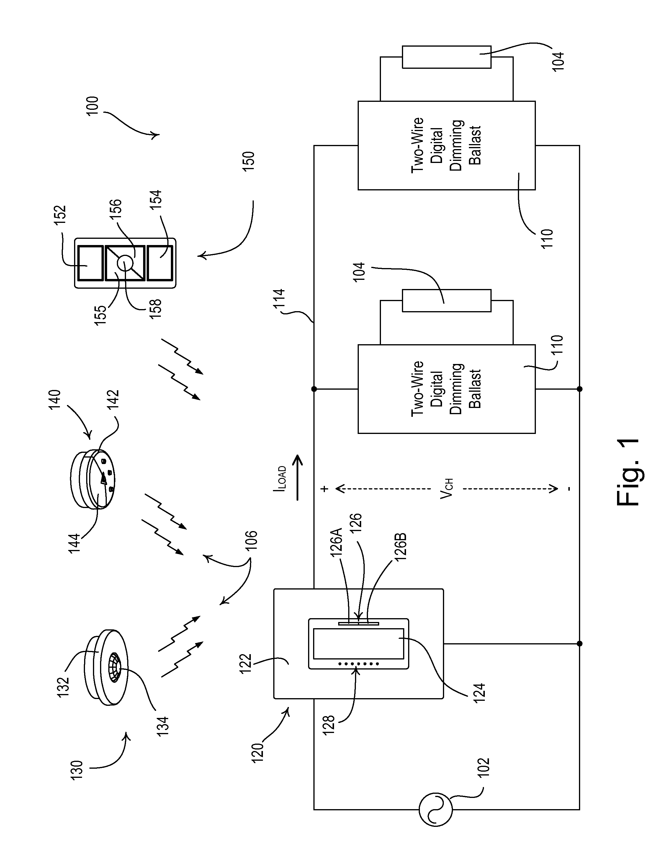
[0076]FIG. 1 is a simple wiring diagram of a load control system 100 having a plurality of two-wire power devices (e.g., two-wire load control devices, such as two-wire digital dimming ballasts 110). The two-wire digital dimming ballasts 110 are coupled to respective lamps 104 for controlling the intensities of the lamps to a desired lighting intensity LDES between a low-end (i.e., minimum) intensity LLE (e.g., approximately 1%) and a high-end (i.e., maximum) intensity LHE (e.g....


PUM


Abstract

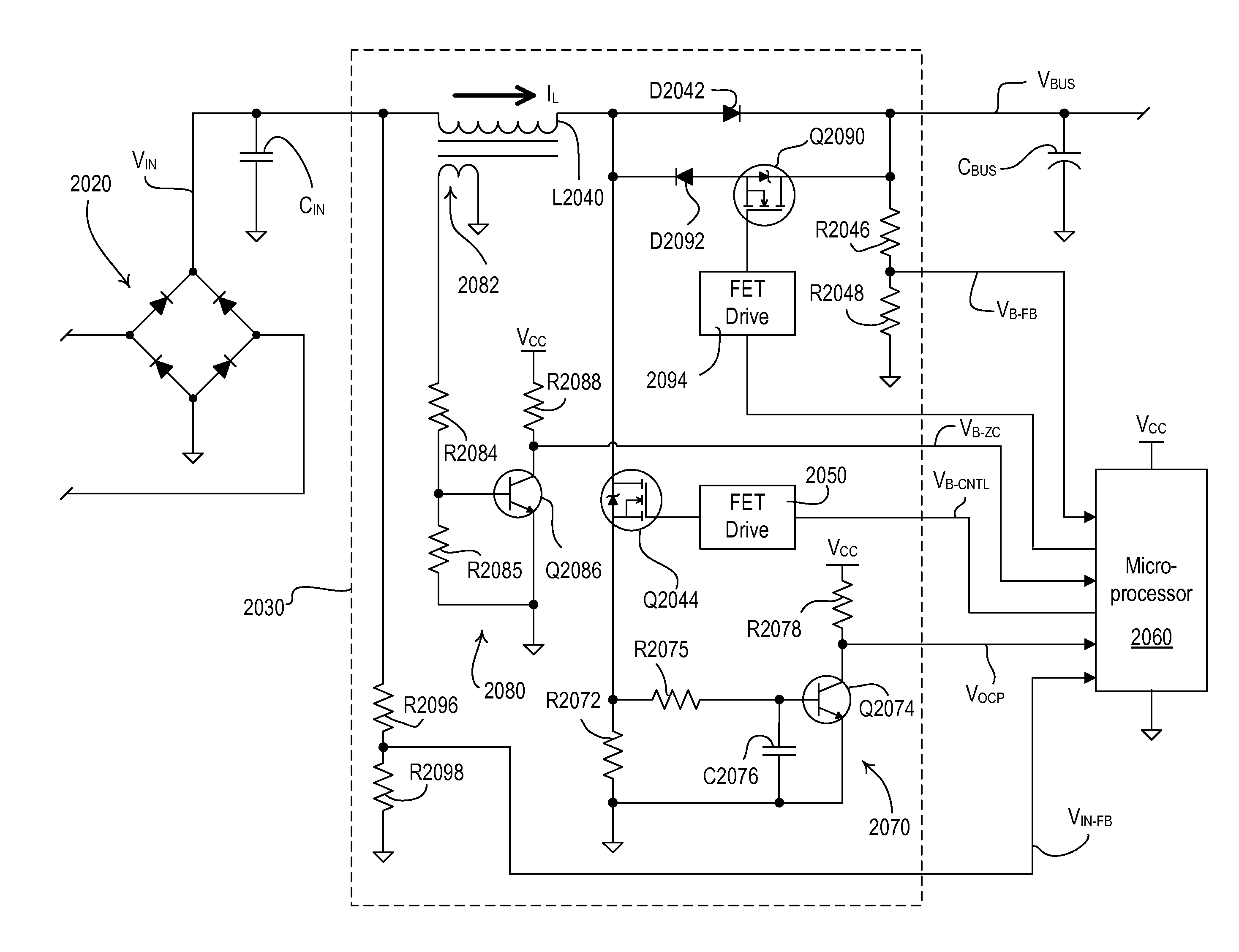
A load control device for controlling the amount of power delivered to an electrical load may include a rectifier circuit configured to receive a phase-control voltage and produce a rectified voltage. A power converter may be configured to receive the rectified voltage at an input and generate a bus voltage. An input capacitor may be coupled across the input of the power converter. The input capacitor may be adapted to charge when the magnitude of the phase control voltage is approximately zero volts. The power converter may be configured to operate in a boost mode, such that the magnitude of the bus voltage is greater than a peak magnitude of the input voltage. The power converter may be configured to operate in a buck mode to charge the input capacitor from the bus voltage when the magnitude of the phase-control voltage is approximately zero volts.

Description

BACKGROUND OF THE INVENTION[0001]1. Field of the Invention[0002]The present invention relates to a load control system for controlling the amount of power delivered to an electrical load, such as a lighting load. More particularly, the present invention relates to a “two-wire” load control system having load control devices that receive both power and communication over two wires from a digital controller that is easily configured without the need for a computer or an advanced commissioning procedure. In addition, the present invention relates to a two-wire load control system having a plurality of load control devices and a digital controller that may be installed in a pre-existing electrical network without requiring any additional wiring. Further, the present invention relates to a two-wire load control system having controllers that respond to a plurality of input devices and transmit digital messages and power over two wires to load control devices without interfering with othe...

Claims


Application Information

Patent Timeline
IPC IPC(8): H05B37/02H05B44/00
CPCH05B37/02H02J13/0024H05B33/0845H05B37/0272H05B37/0227H05B37/0254H05B37/0263H05B37/0218H05B47/185H05B47/11H02J13/00009H02J2310/12H02J13/00004Y02B20/40Y02B90/20Y04S40/121H05B47/115Y04S20/246H05B45/10H05B47/18H05B47/19Y02B70/30H05B47/165H05B47/10H05B47/105
Inventor TAIPALE, MARKBLAKELEY, MATTHEW ROBERTROSS, JOHNATHAN PAULMACADAM, RUSSELL L.
Owner LUTRON TECH CO LLC
Learn More