
Casting delivery nozzle

a delivery nozzle and thin strip technology, applied in the field of thin strip casting, can solve the problems of high heat loss from the casting pool, meniscus marks on the surface of the strip, and inconvenient casting, so as to reduce such surface defects, improve quality, and affect the quality and yield of thin strips

Inactive Publication Date: 2014-09-18
NUCOR CORP
View PDF3 Cites 2 Cited by
  • Summary
  • Abstract
  • Description
  • Claims
  • Application Information

AI Technical Summary

Benefits of technology

The patent text discusses the importance of controlling the flow pattern of molten metal in twin roll casting to improve the quality and yield of thin strip. A smooth flow pattern can prevent surface defects and improve the quality of the finished strip. However, the text also addresses the problem of solid metal forming in the casting pool, which can cause defects in the strip. The text proposes a solution to prevent skimming (the formation of solid metal near the side dams) by controlling the flow of molten metal to the triple point region and inhibiting thinning of the shells on the casting rolls and maintaining the surface of the casting pool. The technical effects of the patent text are to improve the quality and yield of thin strip casting by controlling the flow pattern of molten metal and preventing surface defects.

Problems solved by technology

Further, disturbance of the surface, or meniscus, of the casting pool has a tendency to cause meniscus marks on the surface of the strip.
The formation of pieces of solid metal known as “skulls” in the casting pool in the vicinity of the confining side plates or dams is a known problem.
The rate of heat loss from the casting pool is higher near the side dams adjacent the casting roll ends due to the greater surface area of continuous caster components in contact with the molten metal in the casting pool increasing the conductive heat loss from the system.
However, in providing increased flow in these regions it is important that the surface of the casting pool is disturbed as little as possible.
Also, it is important that the shells are not washed on the casting surfaces of the rolls in the triple point region, increasing the possibility of defects in the strip and reducing the quality and yield of the strip product.

Method used


Image

  • Casting delivery nozzle
  • Casting delivery nozzle
  • Casting delivery nozzle

Examples


Embodiment Construction

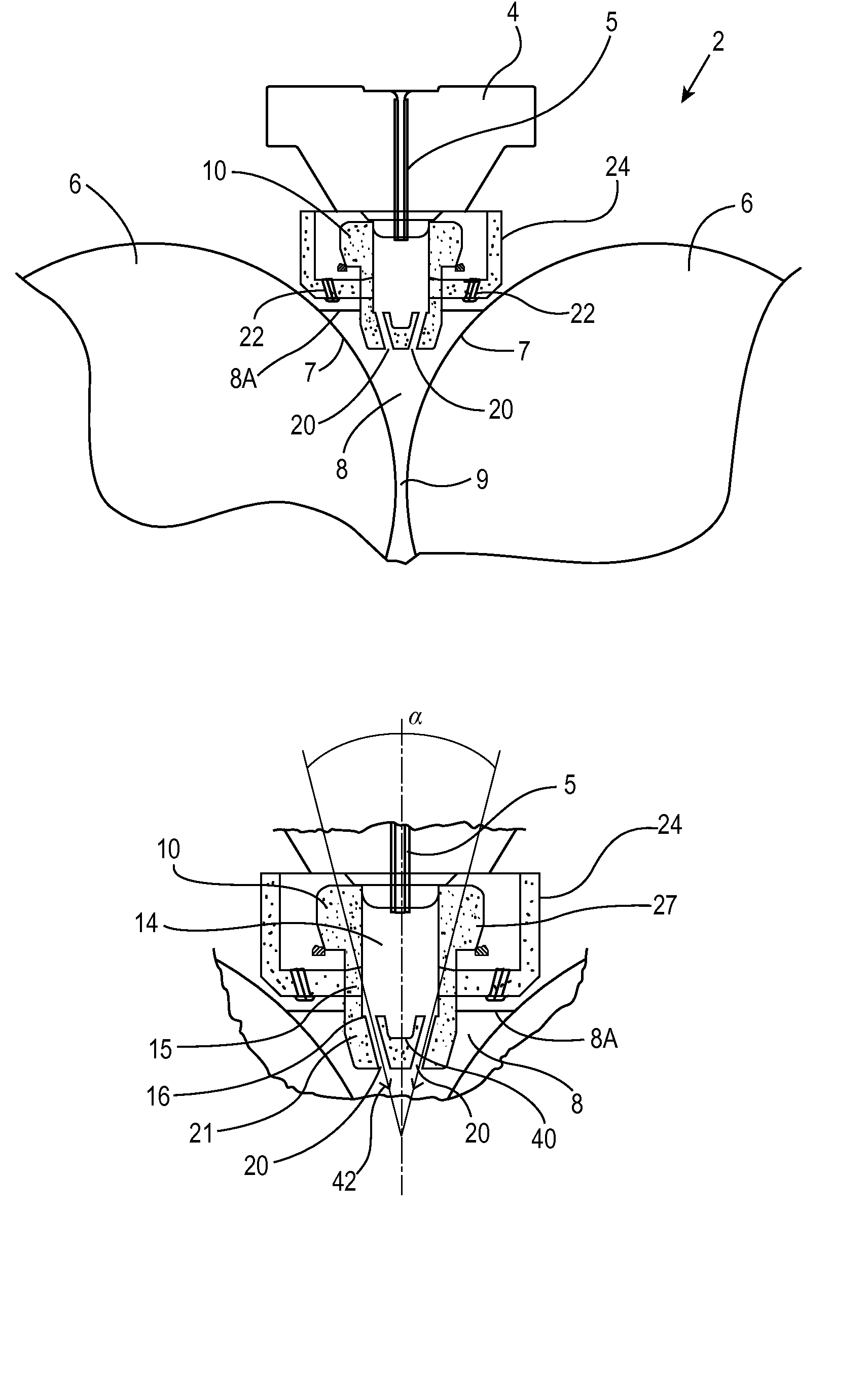
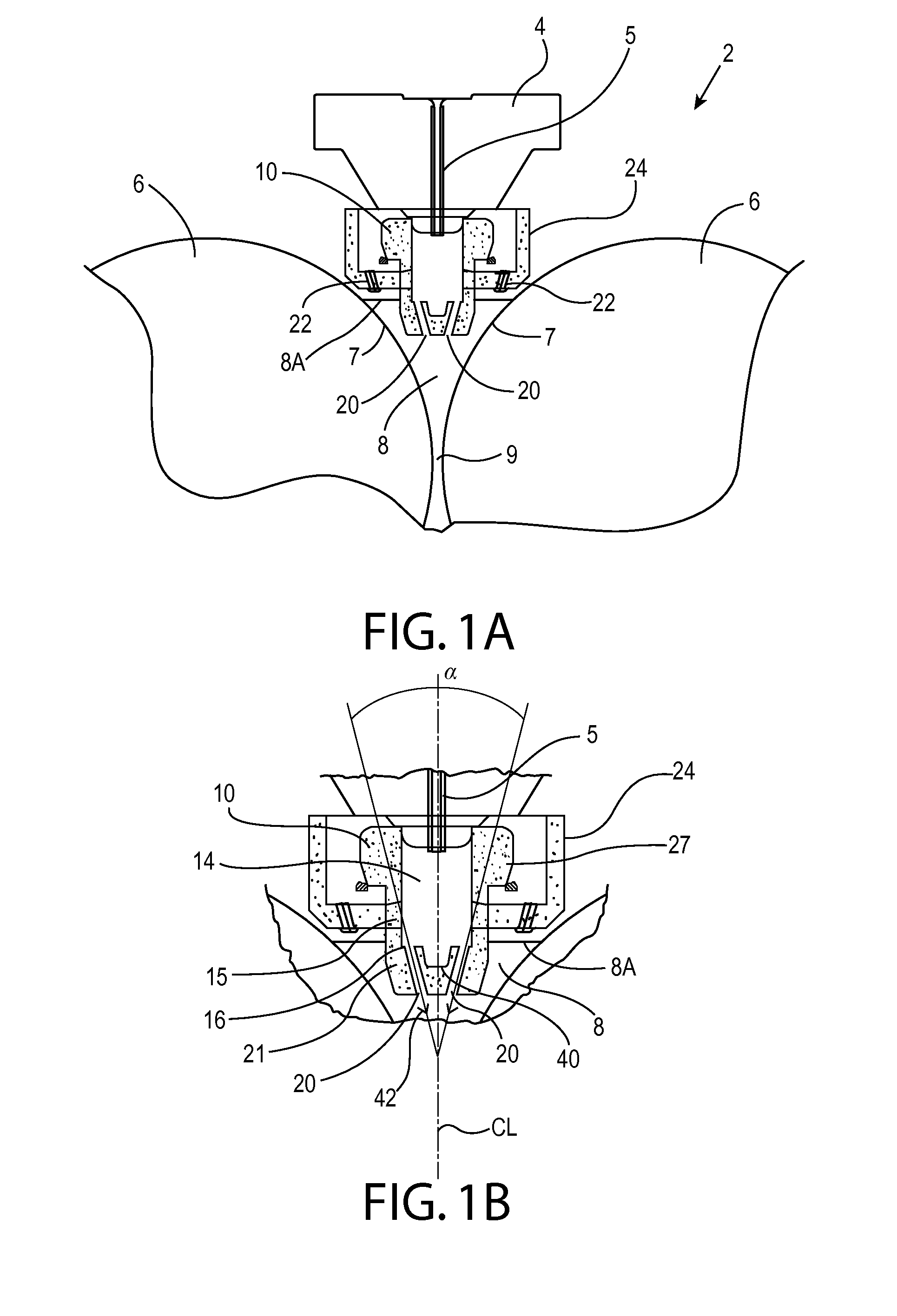
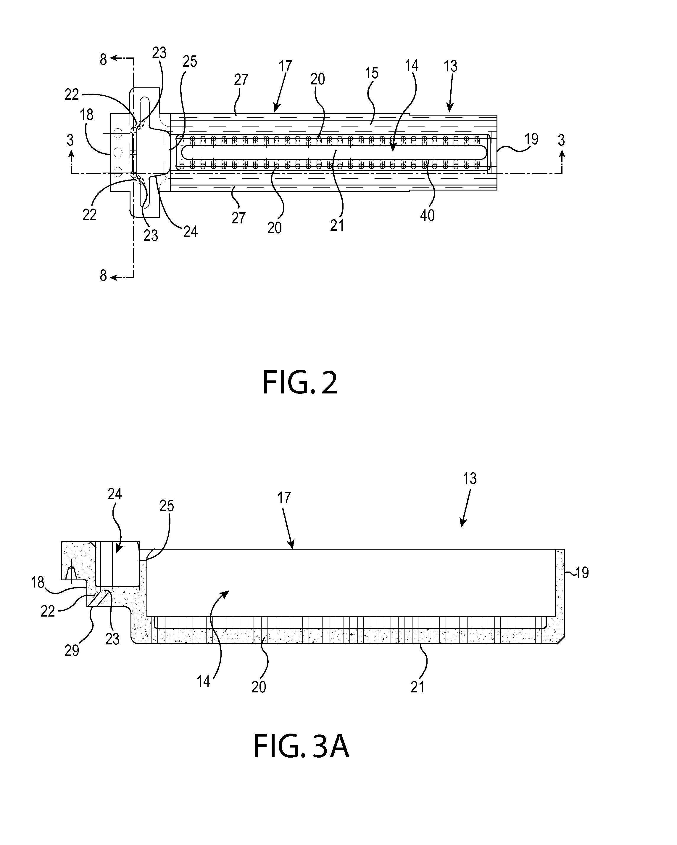
[0059]Disclosed are methods and apparatuses of continuously casting metal strip. Such methods include the steps of assembling a pair of casting rolls laterally disposed to form a nip between them and to maintain a casting pool of molten metal supported by the casting rolls between the side dams, assembling an elongated metal delivery nozzle extending along and above the nip, the delivery nozzle having one or more segments extending longitudinally along the metal delivery nozzle, each segment having a main portion having one or more outlets positioned longitudinally along the elongated metal delivery nozzle and directed downwardly converging toward the nip while forming the casting pool supported on the casting rolls above the nip. The outlets may be positioned as a pair of rows of outlets longitudinally throughout the main portion of the delivery nozzle. The angle of convergence between one row of outlets and the other row of outlets may be such that the direction of flow of molten ...


PUM

PropertyMeasurementUnit
angleaaaaaaaaaa
angleaaaaaaaaaa
angle of convergenceaaaaaaaaaa

Abstract

In a twin roll continuous caster, the casting nozzle in the continuous casting apparatus is arranged such that the outlet passages and / or tapered walls in the main portion within the casting nozzle provide flow of molten metal downwardly converging toward the nip between the casting rolls of a twin roll caster. The casting nozzle having a reservoir portion for directing molten metal converging toward the triple point region to inhibit the washing of shells forming on the casting surfaces of the casting rolls.

Description

RELATED APPLICATIONS[0001]This application is a divisional of U.S. patent application Ser. No. 13 / 710,383, filed Dec. 10, 2012, which claims priority to and the benefit of U.S. Provisional Patent Application No. 61 / 569,001, filed Dec. 9, 2011, which is incorporated herein by reference.BACKGROUND AND SUMMARY[0002]This invention relates to making thin strip and more particularly casting of thin strip by a twin roll caster.[0003]It is known to cast metal strip by continuous casting in a twin roll caster. Molten metal is introduced between a pair of counter-rotating horizontal casting rolls, which are cooled so that metal shells solidify on the moving roll surfaces and are brought together at the nip between the rolls to produce solidified strip product delivered downwardly from the nip between the rolls. The term “nip” is used herein to refer to the general region at which the rolls are closest together. The molten metal may be poured from a ladle into a smaller vessel, or tundish, fro...

Claims


Application Information

Patent Timeline
Patent Type & Authority Applications(United States)
IPC IPC(8): B22D11/06B22D11/103
CPCB22D11/103B22D11/0622B22D11/0642
Inventor MCQUILLIS, GARYKEOWN, KEVINFULBRIGHT, ERIC
Owner NUCOR CORP
Learn More