
Light plate assembly

a technology of light plate and assembly plate, which is applied in the direction of instrumentation, lighting and heating apparatus, planar/plate-like light guides, etc., can solve the problems of obtaining an illuminated area having a relatively large length-to-width ratio with a uniform luminosity along the length of the illuminated area, and light leakage from various locations surrounding such an illuminated area, so as to prevent light leakage in a generally sideways direction and/or minimize the

Inactive Publication Date: 2014-08-28
DAKKOTA LIGHTING TECH
View PDF10 Cites 2 Cited by
  • Summary
  • Abstract
  • Description
  • Claims
  • Application Information

AI Technical Summary

Benefits of technology

This patent text describes a light plate assembly that provides even distribution of light for an illuminated display area. The assembly includes a housing and a trough with a length-to-width ratio greater than 10:1. The trough has a decal strip and a cover with a transparent window that encases the decal strip and prevents light leakage. The cover also has an opaque side edge that bounds the transparent window and prevents unwanted light leakage. The housing and cover are sealed to prevent water intrusion, making the assembly compact and leakage-free. The technical effects of this light plate assembly include minimal light leakage and uniform luminosity for an illuminated display area, making it ideal for use as a component within a compartment such as a passenger vehicle or airplane.

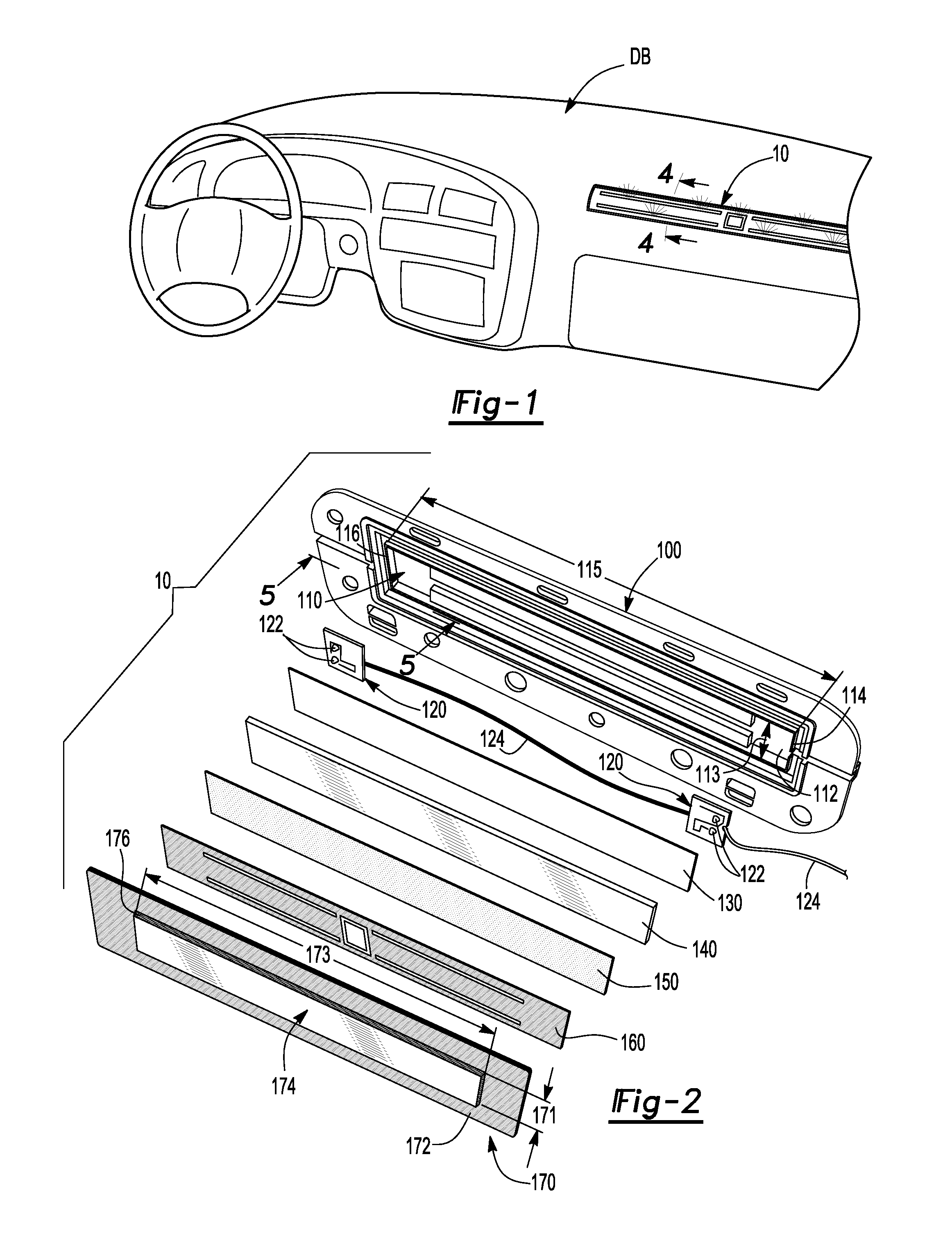
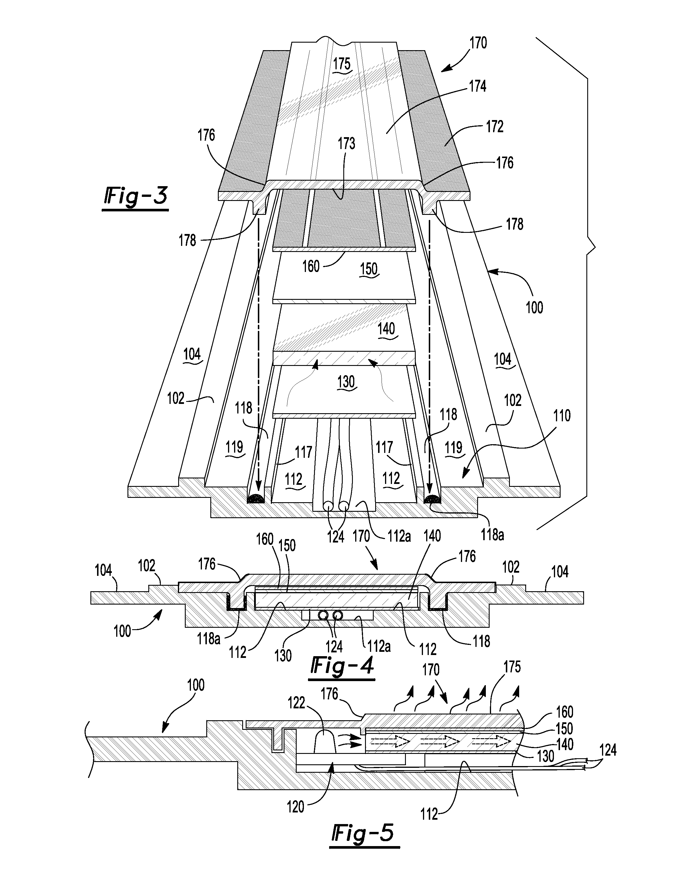
Problems solved by technology

However, obtaining an illuminated area having a relatively large length-to-width ratio with a uniform luminosity along the length of the illuminated area has been problematic.
Furthermore, light leakage from various locations surrounding such an illuminated area has also been problematic.

Method used


Image

  • Light plate assembly
  • Light plate assembly
  • Light plate assembly

Examples


Embodiment Construction

[0013]A light plate assembly that provides uniform luminosity and minimal light leakage is provided. As such, the light plate assembly has utility as a component for use in an interior compartment such as a passenger compartment of a motor vehicle.

[0014]The light plate assembly has a housing that contains one or more light sources, a reflective strip, a light guide plate and an optional decal strip. In combination with a cover, the light plate assembly provides an illuminated area that has a length-to-width ratio greater than 10:1 and a variation in luminosity along the length of the illuminated area of less than 20%.

[0015]The housing can have a trough, i.e. a depression within the housing, that has an elongated base surface with a width and a length. In addition, the length-to-width ratio of the elongated base surface is greater than 10:1. The light source, e.g. a light emitting diode (LED) can be attached to the base surface at a first end and / or a second end of the trough and the...


PUM


Abstract

A light plate assembly having minimal light leakage and uniform luminosity. The light plate assembly has a housing, a trough within the housing and a cover. The cover has a transparent window with an opaque side edge that prevents undesired light leakage between an outer surface of the transparent window and a base frame of the cover. The transparent window also has a length and a width, and a length-to-width ratio of greater than 10:1. In addition, luminosity variation along a length of the transparent window is less than 20%, and in some instances less than 10%.

Description

FIELD OF THE INVENTION[0001]The present invention is related to a light plate assembly, and in particular, to a light plate assembly having uniform luminosity and minimal light leakage.BACKGROUND OF THE INVENTION[0002]Light plate and / or panel assemblies are known. However, obtaining an illuminated area having a relatively large length-to-width ratio with a uniform luminosity along the length of the illuminated area has been problematic. Furthermore, light leakage from various locations surrounding such an illuminated area has also been problematic. Therefore, a light plate assembly having a relatively narrow and long illuminated area with uniform luminosity and minimal light leakage would be desirable.SUMMARY OF THE INVENTION[0003]A light plate assembly having minimal light leakage and uniform luminosity for an illuminated display area having a length-to-width ratio greater than 10:1 is provided. The light plate assembly has a housing and a trough within the housing. The trough has ...

Claims


Application Information

Patent Timeline
IPC IPC(8): F21V8/00
CPCG02B6/0073G02B6/0011
Inventor LICATOVICH, MARK
Owner DAKKOTA LIGHTING TECH
Learn More