Debris evacuator for cleaning a masonry bore

a technology for evacuating debris and masonry, which is applied in the direction of drilling pipes, drilling well accessories, manufacturing tools, etc., can solve the problems of affecting the work efficiency of workers, affecting the safety of workers, and requiring relatively expensive customized drill bits and manifold arrangements

Inactive Publication Date: 2014-08-28
CANEER HADLEY H
View PDF8 Cites 9 Cited by
  • Summary
  • Abstract
  • Description
  • Claims
  • Application Information

AI Technical Summary

Benefits of technology

[0014]The present invention includes a fitting for connection on one end with a longitudinally compressible cover tube to assume variable lengths al...

Problems solved by technology

This then typically involves release of robust plumes of dust and debris to the atmosphere thus resulting in discomfort and health hazards to the workman on site and, as the dust and dirt settles, coated walkways and a generally untidy and dangerous workplace.
Such devices require relatively expensive customized drill b...

Method used


Image

  • Debris evacuator for cleaning a masonry bore
  • Debris evacuator for cleaning a masonry bore
  • Debris evacuator for cleaning a masonry bore

Examples


Embodiment Construction

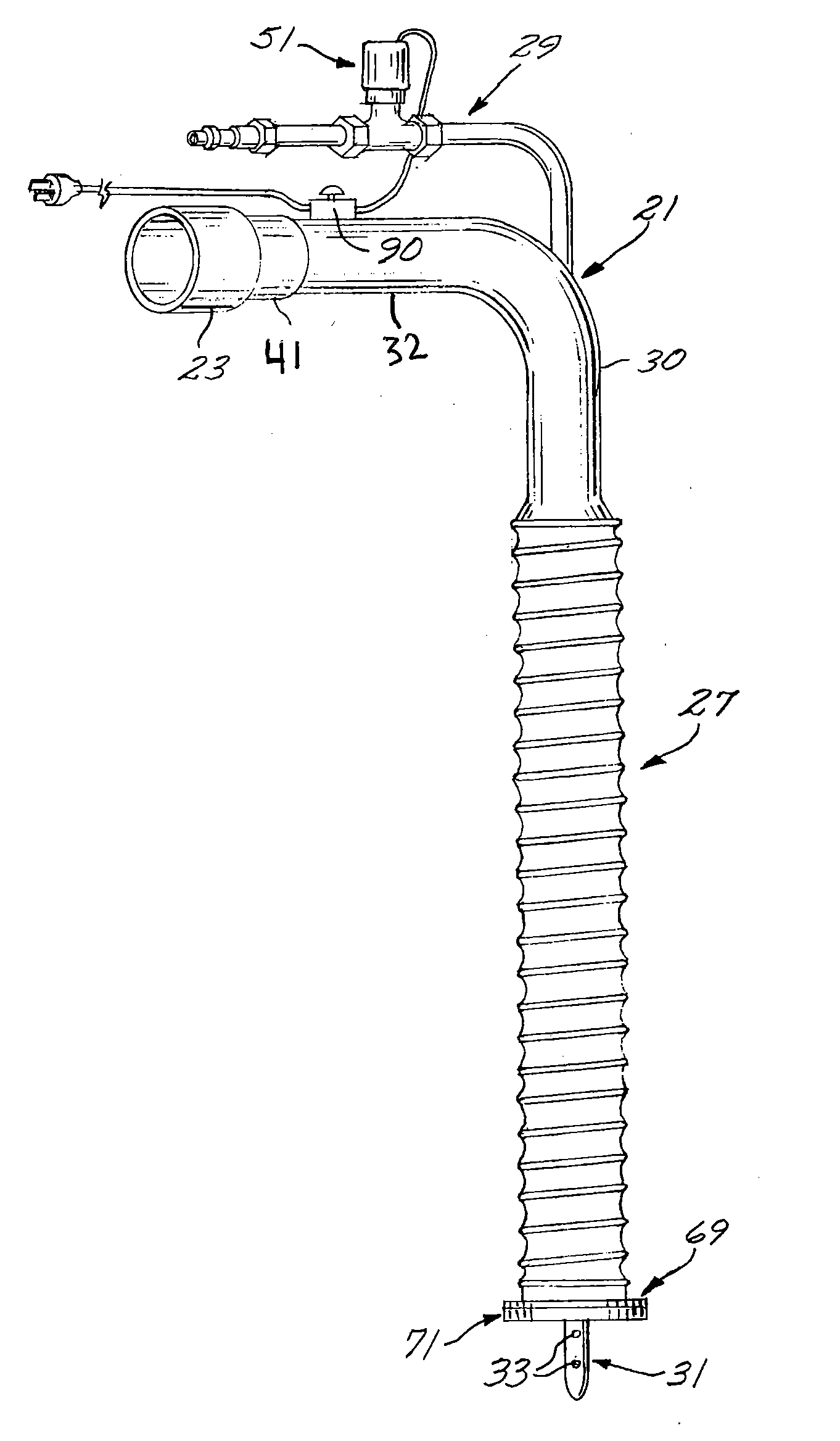
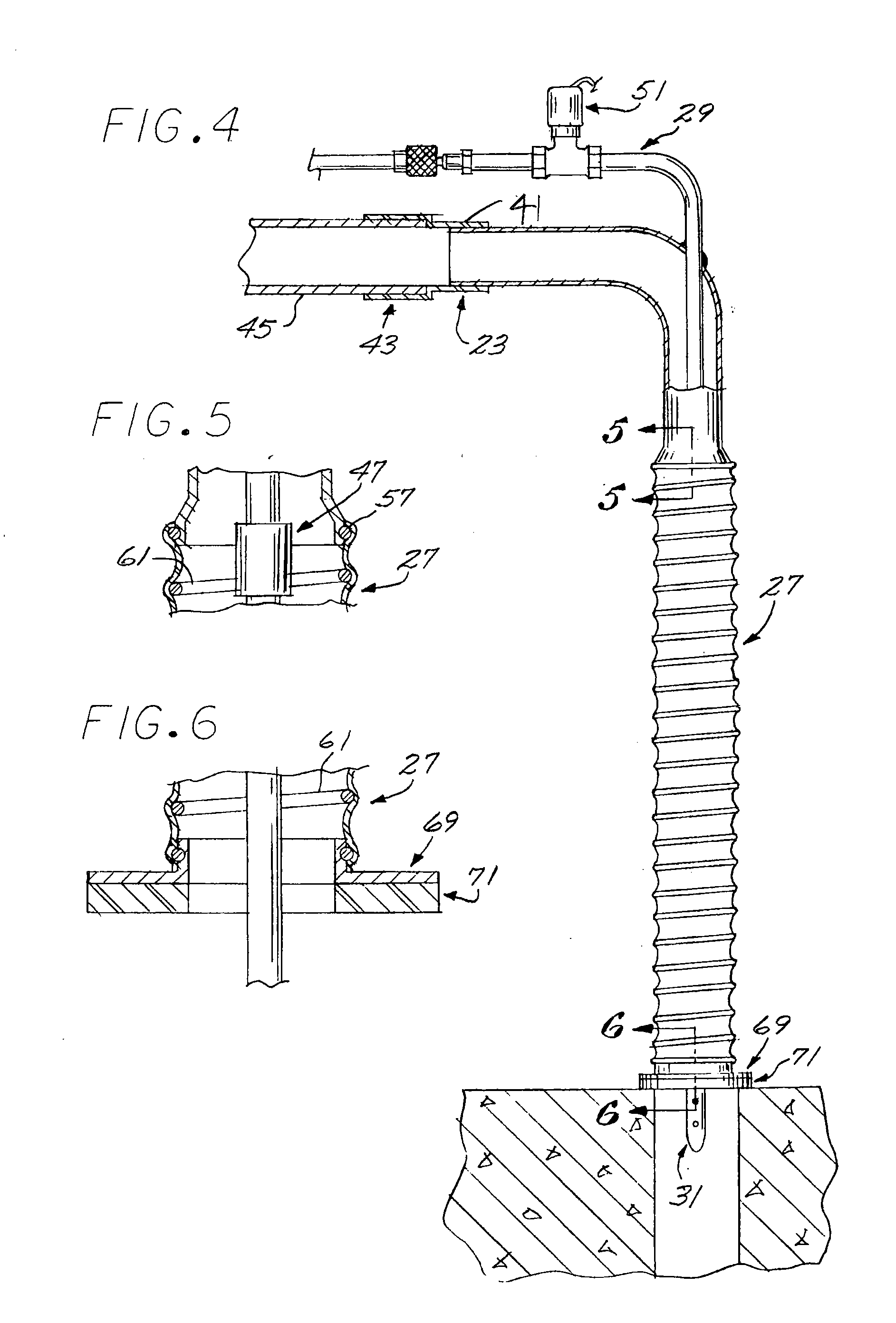
[0023]Referring to FIGS. 1 and 4, the bore cleaning device of the present invention includes, generally, a fitting 21 which may be elbow shaped and is constructed at one end with a vacuum coupling 23 and on the opposite end with a tube connector 25 for connecting with one end of a contractible cover tube 27. Connected with the fitting 21 is a pressure line, generally designated 29, which joins interiorly with one end of a pressure tube 31 configured in its distal side wall with orifices 33 for release of high pressure air in a masonry bore 35 (FIG. 4). Thus, the vacuum coupling 23 may be coupled with a vacuum pump, the pressure line 29 with a compressor and the tube 27 abutted at its distal end over the bore 35 as shown in FIG. 4 and compressed to project the pressure tube 31 into the bore as shown in FIG. 7 to elevate the pressure in such bore while a vacuum is drawn to cooperate in drawing dust and debris from such bore and upwardly through the fitting and to a filtration system c...


PUM


Abstract

A fitting having a cover tube connected to one end and a pressure line in the fitting, connected to a rigid tube projecting from the fitting and through the cover tube. The method includes projecting a rigid tube in a masonry bore, and applying pressurized air to blow debris from the bore to be captured in a cover tube.

Description

[0001]This application is a continuation of U.S. application Ser. No. 13 / 872,508 which was filed May 18, 2010, now U.S. Pat. No. 8,381,841.BACKGROUND[0002]Device for cleaning bore holes.[0003]1. Field of the Invention[0004]The present invention relates to construction tools and particularly to device for cleaning debris from a bore built in concrete.[0005]2. Description of the Prior Art[0006]In construction and remodeling the occasion frequently arises for inserting reinforcement and anchoring dowels which typically requires drilling of bores in concrete foundational or structural side walls. Debris must then be cleaned from the bores for insertion of the dowels and a bonding such as epoxy. This typically involves the insertion of a nozzle or the like in the bore and for the application of high pressured air to swirl the dust and debris about the bore and elevate the particles and chunks by the flow stream generated by high pressure air. This then typically involves release of robus...

Claims


Application Information

Patent Timeline
IPC IPC(8): E21B37/00
CPCB23Q11/0046B23Q11/006A47L9/10B08B5/04Y02P70/10
Inventor CANEER, HADLEY H.
Owner CANEER HADLEY H
Why Eureka
Try Eureka