
Pneumatic tire

a technology of pneumatic tires and cylinders, applied in the field of pneumatic tires, can solve the problems of uneven wear, corner first contact with the road to be rounded, and the advantage of facilitating the deformation of curved grooves, so as to suppress the occurrence of uneven wear and reduce the effect of driving nois

Active Publication Date: 2014-08-28
TOYO TIRE & RUBBER CO LTD
View PDF3 Cites 34 Cited by
  • Summary
  • Abstract
  • Description
  • Claims
  • Application Information

AI Technical Summary

Benefits of technology

The present invention is providing a pneumatic tire that can reduce driving noise by reducing uneven wear (especially in the heel and toe areas). The tire has an asymmetrical pattern with a plurality of F-shaped blocks arranged adjacent to each other in the tire-circumferential direction. Each F-shaped block has a stem, a first branch, and a second branch. A first small block is interposed between the first branch of one of each two adjacent F-shaped blocks and a second small block is surrounded by the stem, the first branch, and the second branch of each F-shaped block. The first and second branches have a relatively high stiffness, while the first and second small blocks have a relatively low stiffness. This configuration can improve tire performance by reducing uneven wear and noise while maintaining good traction and stability.

Problems solved by technology

However, it is disadvantageous to facilitate the deformation of the curved groove, when driving a vehicle on a dry road.
Such wear causes the corner that first comes into contact with the road to be rounded.
Such uneven wear becomes significant as the travel distance of the vehicle increases.
This increases the driving noise.
For this reason, there is a concern that the driver of the vehicle is made to feel uncomfortable.

Method used


Image

  • Pneumatic tire
  • Pneumatic tire
  • Pneumatic tire

Examples


embodiment

Configuration and Action of Embodiment

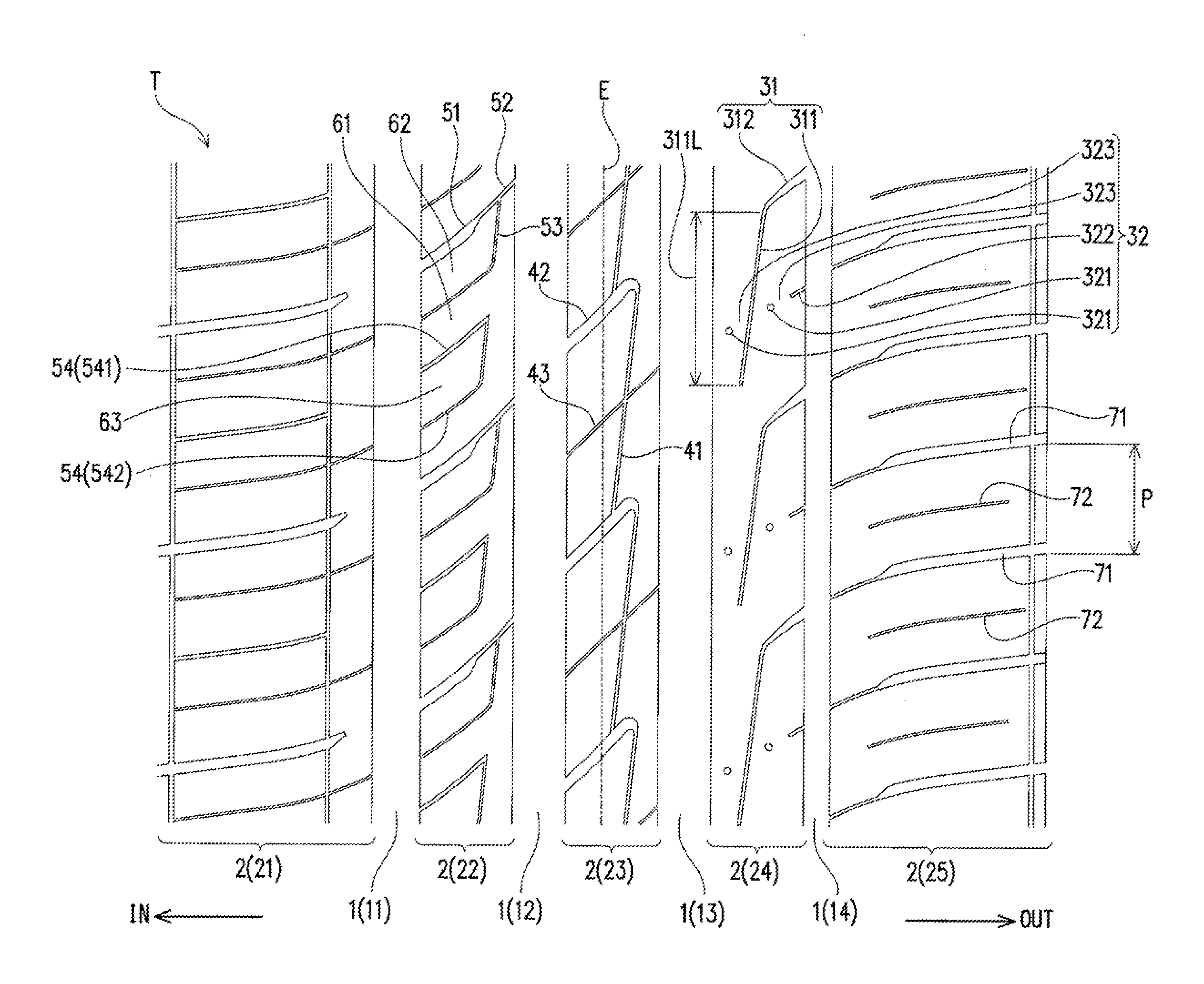
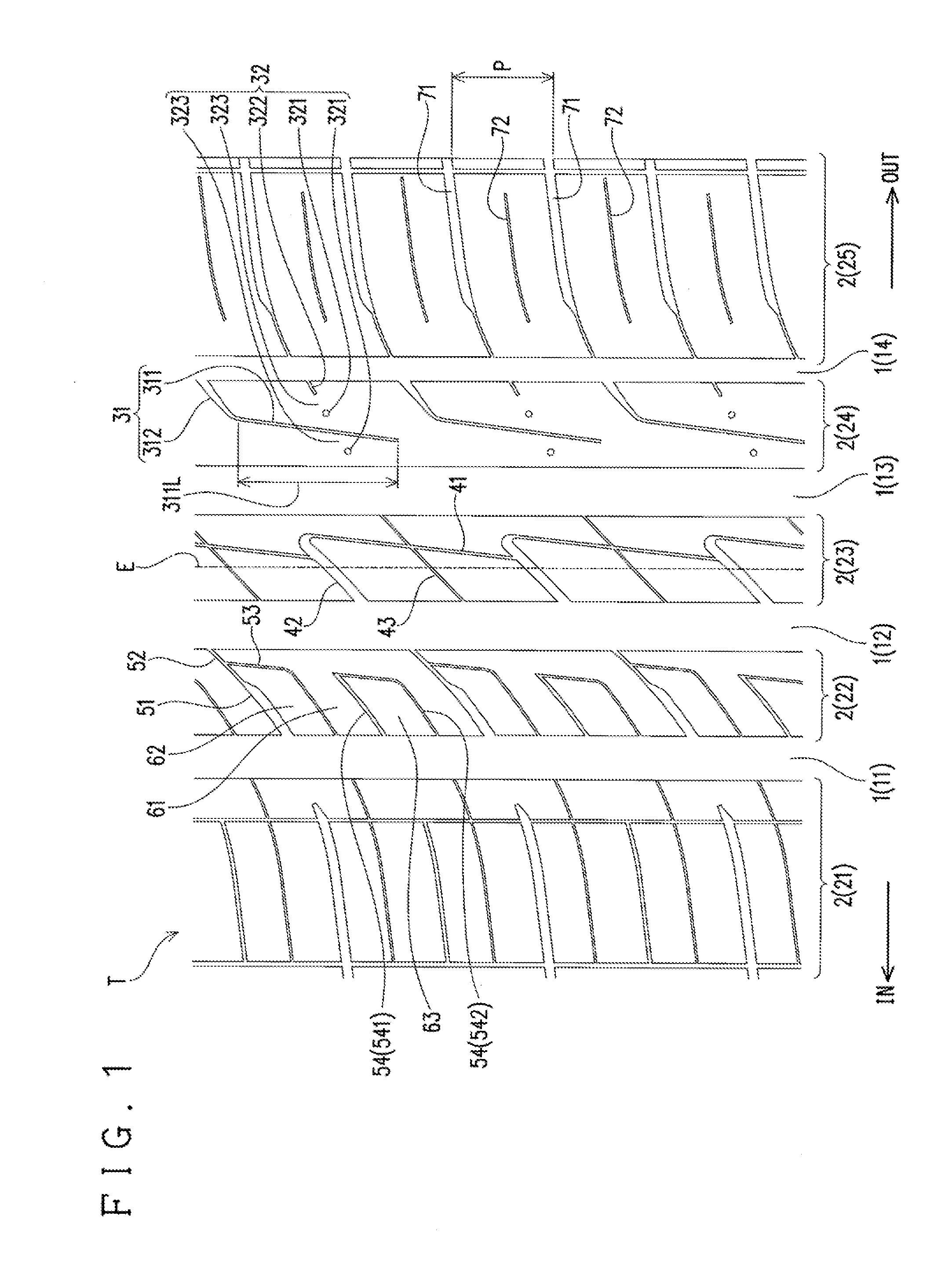
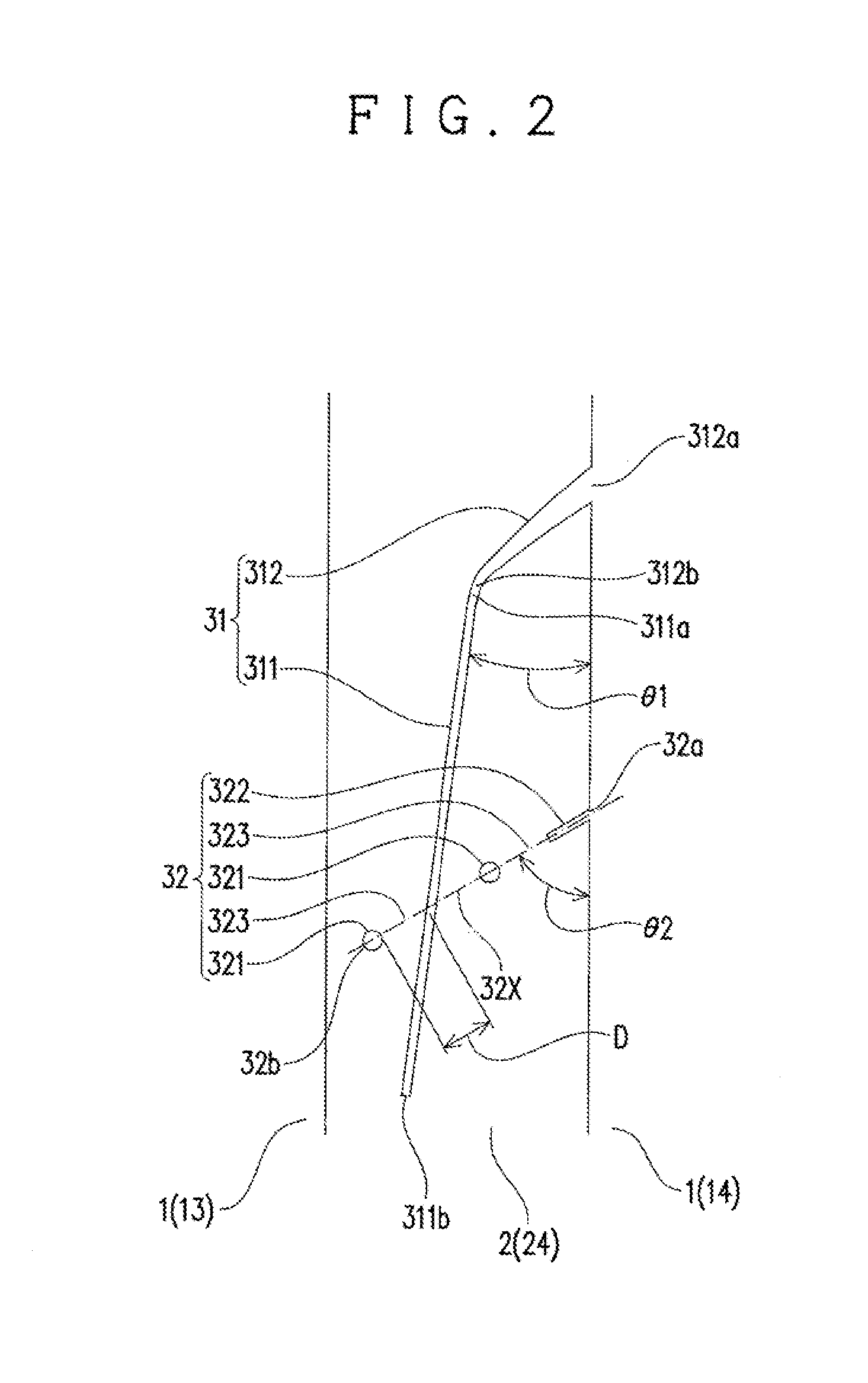
[0088]Finally, the configuration of the aforementioned embodiment and actions exerted by the configuration are summarized. The present invention provides a pneumatic tire including a tread T with a rib pattern, in which: the tread T includes at least one main groove 1 extending in the tire-circumferential direction, and a plurality of ribs 2, formed by the at least one main groove 1, extending in the tire-circumferential direction; at least one (the outer intermediate rib 24) of the plurality of ribs 2 has a plurality of narrow grooves 31 formed at intervals in the tire-circumferential direction; one or a plurality of intermittent sipes 32 are formed corresponding to at least one of the plurality of narrow grooves 31; the plurality of narrow grooves 31 are a plurality of grooves each having a groove width smaller than the at least one main groove 1 and having a portion extending substantially along the tire-circumferential direction; the intermi...


PUM


Abstract

A pneumatic tire includes a tread having at least one main groove and a plurality of ribs extending in the tire-circumferential direction. At least one of the ribs has a plurality of narrow grooves formed at intervals in the tire-circumferential direction. At least one intermittent sipe is formed corresponding to at least one of the narrow grooves. The narrow grooves are grooves each having a portion extending substantially along the tire-circumferential direction and having a groove width smaller than the at least one main groove. The at least one intermittent sipe has a plurality of holes that are intermittently formed, and at least one solid part located between adjacent two of the holes. The holes and the solid part are arranged in a direction intersecting the narrow grooves. The intermittent sipe intersects the corresponding narrow groove in the at least one solid part.

Description

CROSS-REFERENCE TO RELATED APPLICATION[0001]This application claims priority to Japanese Patent Application No. 2013-033375, the disclosure of which is incorporated herein by reference in its entirety.BACKGROUND OF THE INVENTION[0002]1. Field of the Invention[0003]The present invention relates to a pneumatic tire including a tread with a rib pattern.[0004]2. Background Art[0005]There have been proposed various structures for a rib pattern included in a tread of an pneumatic tire. Examples thereof include a pattern structure disclosed in JP 2009-292252 A.[0006]As shown in FIG. 1 of JP 2009-292252 A, this pattern structure includes a rib formed, in the center region of the tread, as a land area interposed between two main grooves extending in the tire-circumferential direction. A narrow groove extending in the tire-circumferential direction is formed at the center in the tire-width direction of the rib (in coincidence with the tire equator). A plurality of curved grooves extend from e...

Claims


Application Information

Patent Timeline
Patent Type & Authority Applications(United States)
IPC IPC(8): B60C11/12B60C11/03
CPCB60C11/1236B60C11/0304B60C11/032B60C2011/0341B60C2011/0388B60C2011/1209B60C2011/0381
Inventor TAKAHASHI, TOSHIHIKO
Owner TOYO TIRE & RUBBER CO LTD
Learn More