
Filter unit

Active Publication Date: 2014-08-28
CAMFIL
View PDF3 Cites 12 Cited by
  • Summary
  • Abstract
  • Description
  • Claims
  • Application Information

AI Technical Summary

Benefits of technology

The present invention provides a filter unit that simplifies the insertion and removal of filter pockets, making it easier and more convenient to replace or repair filters. The filter unit is easily foldable and can be stored or transported in a compact way. The frame and support structure act to stretch the filter bag, providing a large pre-filter pocket area for filtering air or gas. The filter unit is efficient in removing particles from the air or gas flow and has a long service life compared to other arrangements. The frame and support structure also prevent a bulging deformation of the filter bag and avoid a contact between adjacent filter units, which may decrease filter efficiency and wear.

Problems solved by technology

With this, potential damage risks such as e.g. turbine fouling, corrosion, and adhesion of the particles to the rotor blades in the gas turbine air compressing device may be impeded.
After a certain time of operation, dependent on the ambient conditions in which the gas turbine operates, a large quantity of accumulated particles in the filters deteriorate the function of the intake device.
In other words, the air or gas flow resistance increases which may, as a consequence, result in an electricity output loss of the gas turbine.
Moreover, other ambient conditions such as sand storms, snow storms, rain, heat, cold, or the like may negatively affect the performance of the filters.
However, a filter replacement may raise several problems.
If the filter is removed from an intake device during gas turbine operation, the prevention of particles entering the gas turbine at the air intake is impaired.
Such a particle intrusion into the gas turbine may lead to a deteriorated gas turbine operation, costly maintenance, and / or possibly, a gas turbine breakdown.
However, this approach leads to other problems, as ruptures in gas turbine operation usually are cumbersome and problematic.
Furthermore, a gas turbine switch-off, leading to an operation standstill, is associated with an economic loss.
However, as the handling of the pocket filter assembly disclosed may be relatively cumbersome, alternative solutions for a more convenient arrangement for particle removal may be of interest.

Method used


Image

  • Filter unit
  • Filter unit
  • Filter unit

Examples


Embodiment Construction

[0056]In the following description, the present invention is described with reference to a filter unit for removing particles from an air or gas flow.

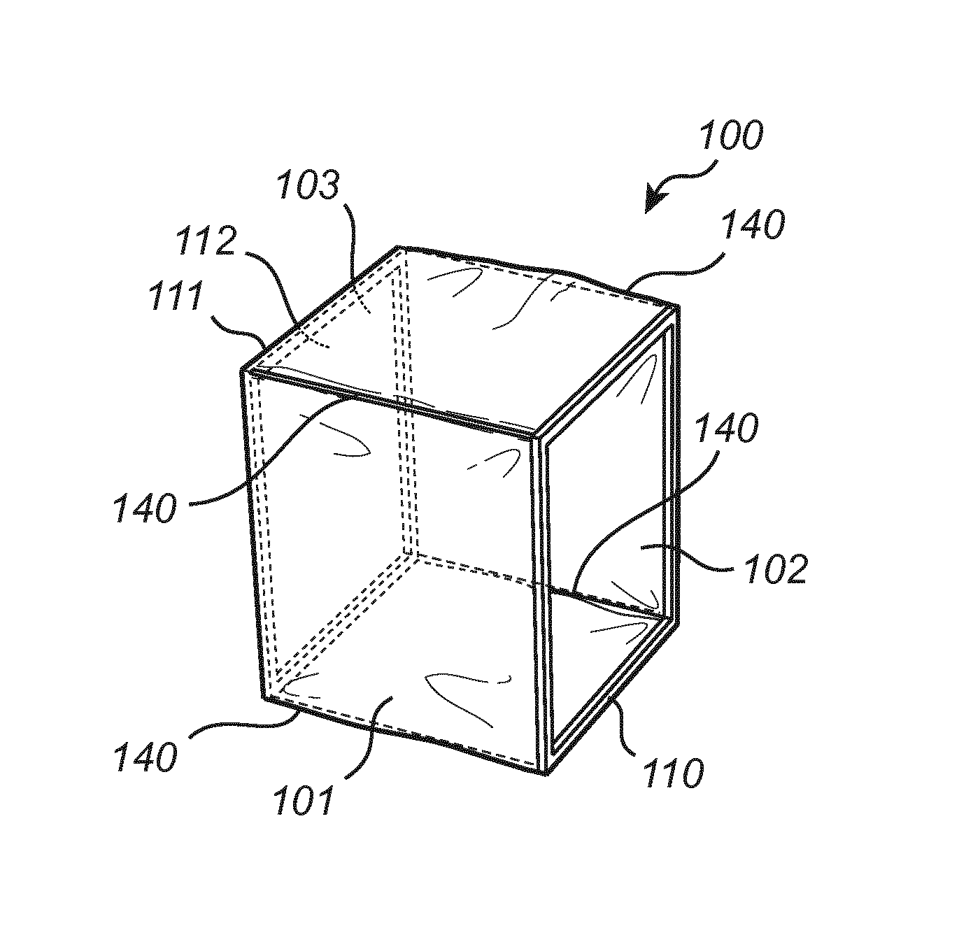
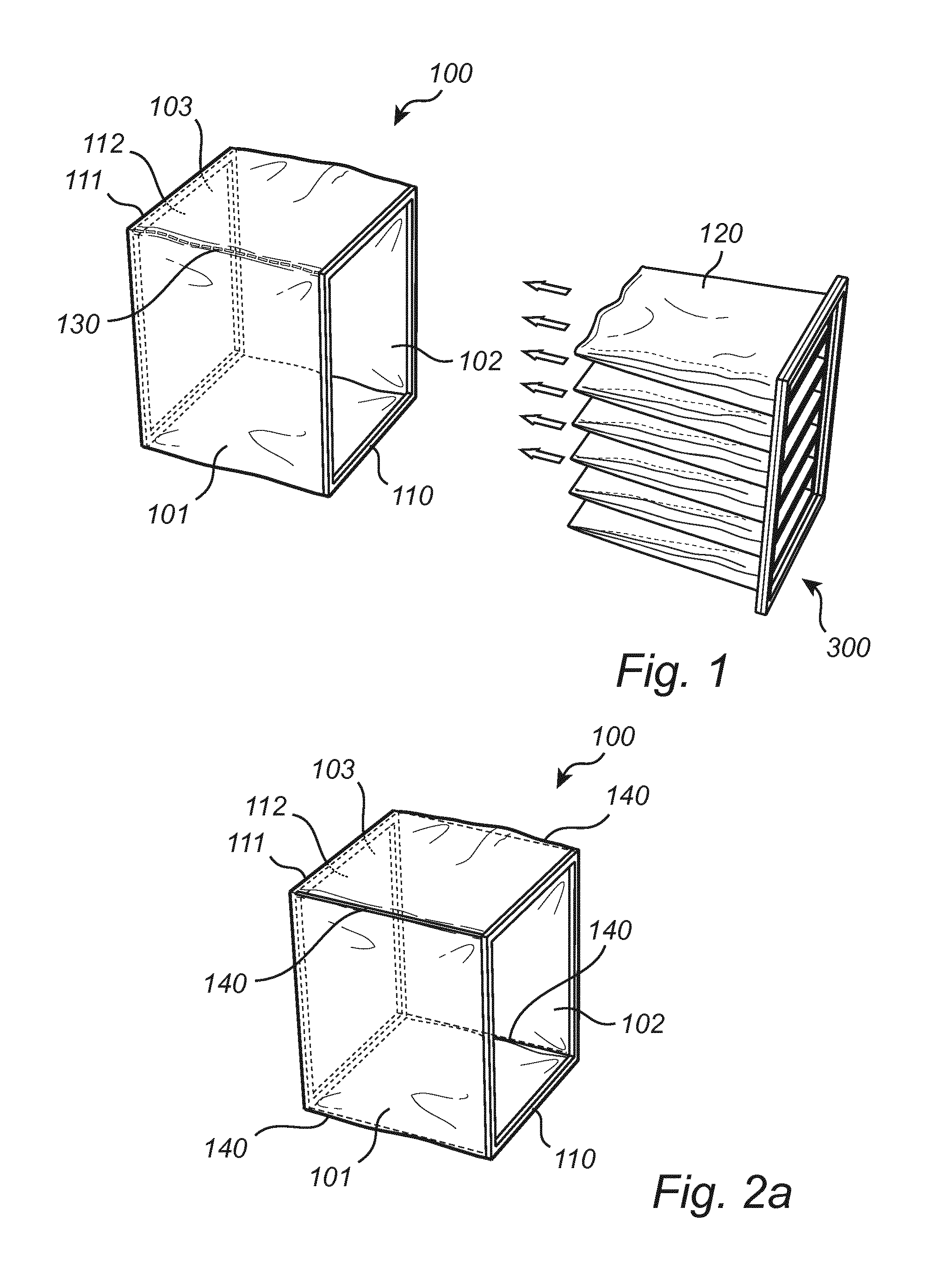
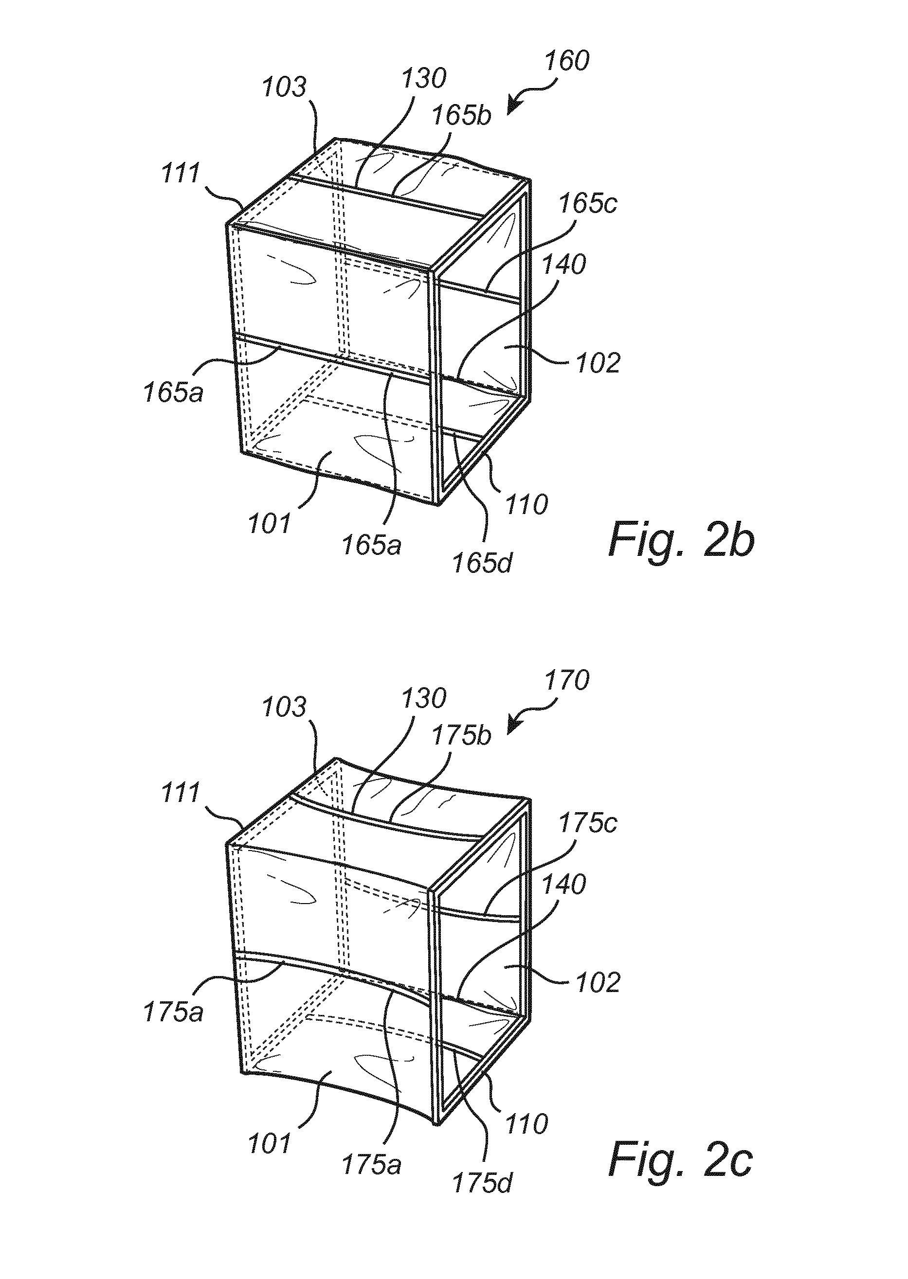
[0057]FIG. 1 is a perspective view of a filter unit 100 comprising a filter bag 101 with filter material for removing particles from an air or gas flow. The filter bag 101 comprises an opening portion 102, i.e. a mouth of the filter bag 101. Opposite the opening portion 102 is arranged an end portion 103, being a portion of the bottom / closed end of the filter bag 101 and facing the opening portion 102. In FIG. 1, the opening portion 102 and the end portion 103 are substantially quadratic. A frame 110 is arranged around the periphery of the opening portion 102, the frame 110 thereby defining the opening portion 102 of the filter bag 101. The frame 110 is substantially quadratic and the plane of the frame 110 is perpendicular to the air or gas flow during operation. The frame 110 is preferably rigid, and may comprise a lightweight struct...


PUM

PropertyMeasurementUnit
Fractionaaaaaaaaaa
Fractionaaaaaaaaaa
Lengthaaaaaaaaaa

Abstract

A filter unit comprising a filter bag for removing particles from an air or gas flow, wherein the filter unit is arranged to receive at least one filter pocket and the filter bag comprises an opening portion and an end portion opposite said opening portion. The filter unit further comprises a frame arranged at a periphery of the opening portion, and a support structure arranged at the periphery of the end portion for stretching an area of the end portion. The frame and the support structure act to stretch the filter bag into a substantially parallelepiped shape such that the filter unit is arranged to provide a free passage for the at least one 140 filter pocket into and out of said filter bag. Furthermore, the filter unit is arranged to fold between the frame and the support structure into a folded state.

Description

FIELD OF THE INVENTION[0001]The present invention relates to a filter unit for removing particles from an air or gas flow, wherein the filter unit may be provided in any air treatment system, e.g. in an air intake device of a gas turbine.BACKGROUND OF THE INVENTION[0002]Filters are often used to remove solid particles such as e.g. dust, pollen, mold, or sand from an air flow. Especially in applications where air quality is important, notably in building ventilation systems and in engines, filters are often indispensible for the provision of clean air. For example, gas turbines are generally operated with filters for removing particles from an air or gas flow, such that particles are hindered to enter the turbine. With this, potential damage risks such as e.g. turbine fouling, corrosion, and adhesion of the particles to the rotor blades in the gas turbine air compressing device may be impeded. Thus, the filters are provided to maintain the functionality of an electricity generation o...

Claims


Application Information

Patent Timeline
IPC IPC(8): B01D46/02
CPCB01D46/023B01D46/02B01D46/0016B01D2275/203B01D46/64B01D46/62B01D46/58
Inventor KOHN, JOSHUALANS, ERIK
Owner CAMFIL
Learn More