
Face-lit waveguide illumination systems

a waveguide and illumination system technology, applied in lighting and heating apparatus, instruments, holographic processes, etc., can solve the problems of difficult to input light from a relatively large source, many existing structural or artistic objects which can provide light guiding and distribution functions are not always readily transformable to edge-lit applications, and otherwise impractical to input light through an edg

Active Publication Date: 2014-08-14
S V V TECH INNOVATIONS
View PDF49 Cites 93 Cited by
  • Summary
  • Abstract
  • Description
  • Claims
  • Application Information

AI Technical Summary

Benefits of technology

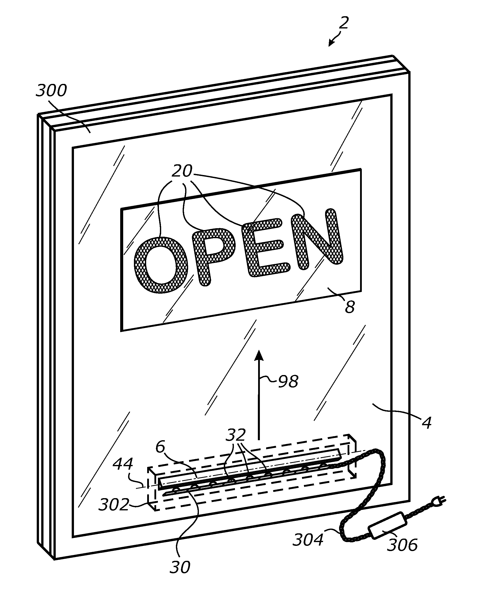
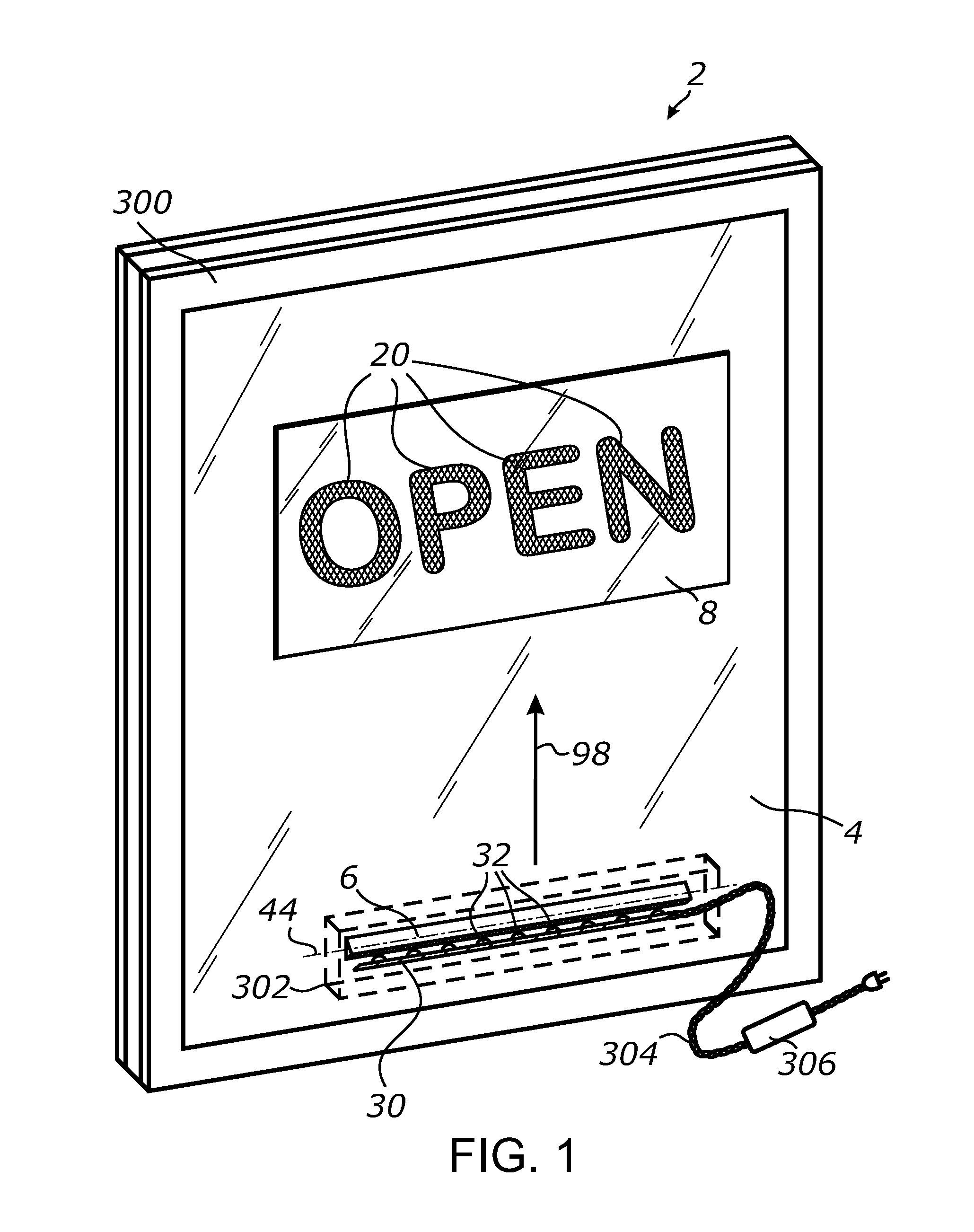
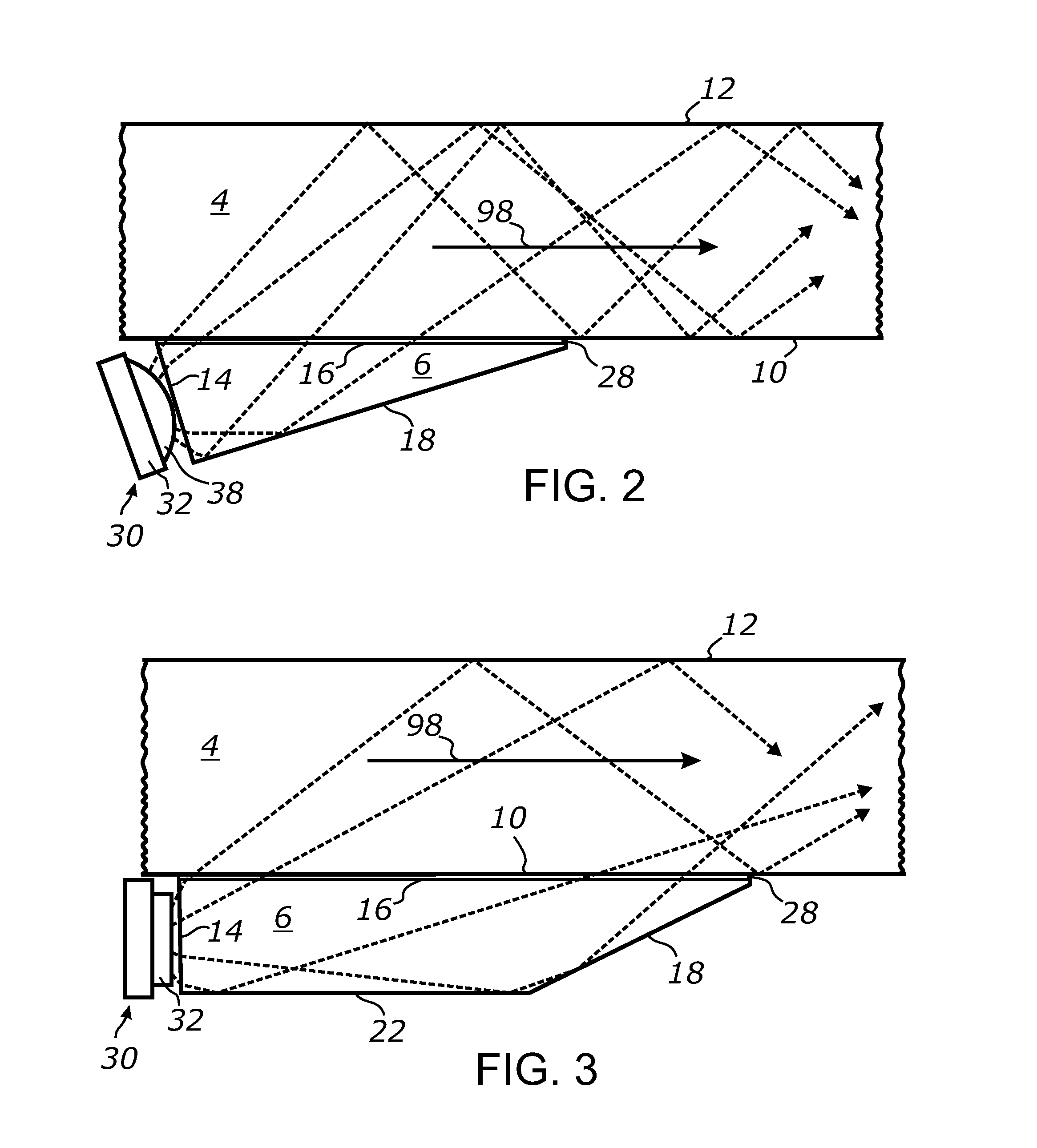
The invention solves problems with traditional edge-lit illumination devices by providing a face-lit solution. The system uses a planar optical waveguide, which allows for controlled light input at one location and allows for light to be propagated along the waveguide and then extracted from another location. The invention also includes linear LED arrays and light extracting features that direct light from the waveguide towards a surface for improved visibility.

Problems solved by technology

However, a number of applications exist where edges of the waveguide are not accessible or it is otherwise impractical to input light through an edge.
Furthermore, many existing structural or artistic articles which can provide light guiding and distribution functions are not always readily transformable to edge-lit applications.
In a yet further example, the edges of some transparent slabs or panels may be tapered making it difficult to input light from a relatively large source.
The light input aperture of edges may also be too small compared to the size of the light source due to the insufficient thickness of the transparent slab or panel.

Method used


Image

  • Face-lit waveguide illumination systems
  • Face-lit waveguide illumination systems
  • Face-lit waveguide illumination systems

Examples


Embodiment Construction

[0049]Referring more specifically to the drawings, for illustrative purposes the present invention is embodied in the system generally shown in the preceding figures. It will be appreciated that the system may vary as to configuration and as to details of the parts without departing from the basic concepts as disclosed herein. Furthermore, elements represented in one embodiment as taught herein are applicable without limitation to other embodiments taught herein, and in combination with those embodiments and what is known in the art.

[0050]A wide range of applications exist for the present invention in relation to the collection and distribution of electromagnetic radiant energy, such as light, in a broad spectrum or any suitable spectral bands or domains. Therefore, for the sake of simplicity of expression, without limiting generality of this invention, the term “light” will be used herein although the general terms “electromagnetic energy”, “electromagnetic radiation”, “radiant ene...


PUM


Abstract

A face-lit waveguide illumination system employing a planar slab or plate of an optically transmissive material. A light source is optically coupled a linear optical element which is attached to a face of the waveguide and is configured to inject light at an angle permitting for light propagation by means of a total internal reflection. Light is propagated through the waveguide towards a predetermined direction in response to optical transmission and total internal reflection. Light extraction features located along the prevailing path of light propagation extract light from the waveguide and emit such light towards a surface perpendicular. In one embodiment, the planar waveguide includes a window pane which provides light transport from one location, where light is injected through the face of the pane, to another location where light is extracted. Additional embodiments of the face-lit waveguide illumination system are also disclosed.

Description

CROSS-REFERENCE TO RELATED APPLICATIONS[0001]This application claims priority from U.S. provisional application Ser. No. 61 / 598,854 filed on Feb. 14, 2012, incorporated herein by reference in its entirety.STATEMENT REGARDING FEDERALLY SPONSORED RESEARCH OR DEVELOPMENT[0002]Not ApplicableINCORPORATION-BY-REFERENCE OF MATERIAL SUBMITTED ON A COMPACT DISC[0003]Not ApplicableNOTICE OF MATERIAL SUBJECT TO COPYRIGHT PROTECTION[0004]A portion of the material in this patent document is subject to copyright protection under the copyright laws of the United States and of other countries. The owner of the copyright rights has no objection to the facsimile reproduction by anyone of the patent document or the patent disclosure, as it appears in the United States Patent and Trademark Office publicly available file or records, but otherwise reserves all copyright rights whatsoever. The copyright owner does not hereby waive any of its rights to have this patent document maintained in secrecy, inclu...

Claims


Application Information

Patent Timeline
IPC IPC(8): F21V7/00F21V8/00
CPCF21V7/0091G02B6/0025G02B6/003G02B6/0095G02B6/0068G02B6/0073G02B6/009G02B6/006G09F13/18G03H2223/16G02B6/0076G02B6/0028G02B6/0075G02B6/0015G02B6/0023G02B6/4214G09F13/049F21V2200/20G02B6/0031
Inventor VASYLYEV, SERGIY VICTOROVICH
Owner S V V TECH INNOVATIONS
Learn More