
Inflatable box and method of use thereof

a technology of inflatable boxes and boxes, which is applied in the field of cushioning, can solve the problems of waste disposal and recycling problems, ineffective methods, and inconvenient use of prior art devices, and achieve the effects of increasing the safety of using inflatable devices, reducing the weight of the package, and improving safety

Inactive Publication Date: 2014-08-14
SMITH JACK V
View PDF16 Cites 19 Cited by
  • Summary
  • Abstract
  • Description
  • Claims
  • Application Information

AI Technical Summary

Benefits of technology

The present invention provides an improved method and apparatus for packaging items for shipment. The invention is simple to use, requires minimal instruction, and has a minimal number of parts. The invention also provides a cost-effective solution. The packaging is easy to inflate and deflate, and it provides a safe and efficient way to cushion items during shipment. The invention is advantageous over previous methods that require multiple steps and cushions. Overall, the invention improves the safety and efficiency of inflatable packaging.

Problems solved by technology

However, all of the packaging materials mentioned can cause waste disposal and recycling issues.
While the prior art provides protection to the articles within a box, the conventional art suffers from a number of drawbacks.
The inflation, insertion, and closure of the prior art devices all require multiple steps and are not simple, efficient methods of shipping articles or products using an inflatable cushion.
The prior art requires tedious methods for inflation.

Method used


Image

  • Inflatable box and method of use thereof
  • Inflatable box and method of use thereof
  • Inflatable box and method of use thereof

Examples


example 1

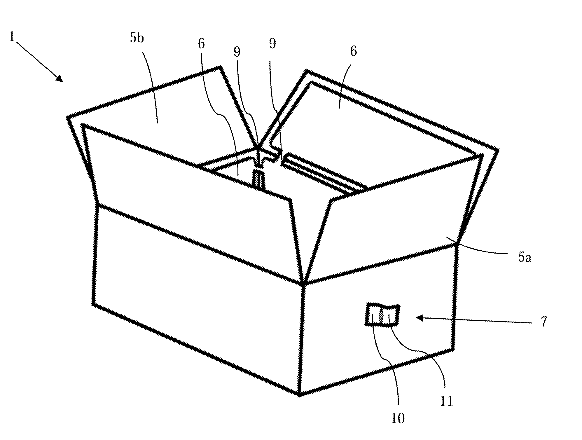
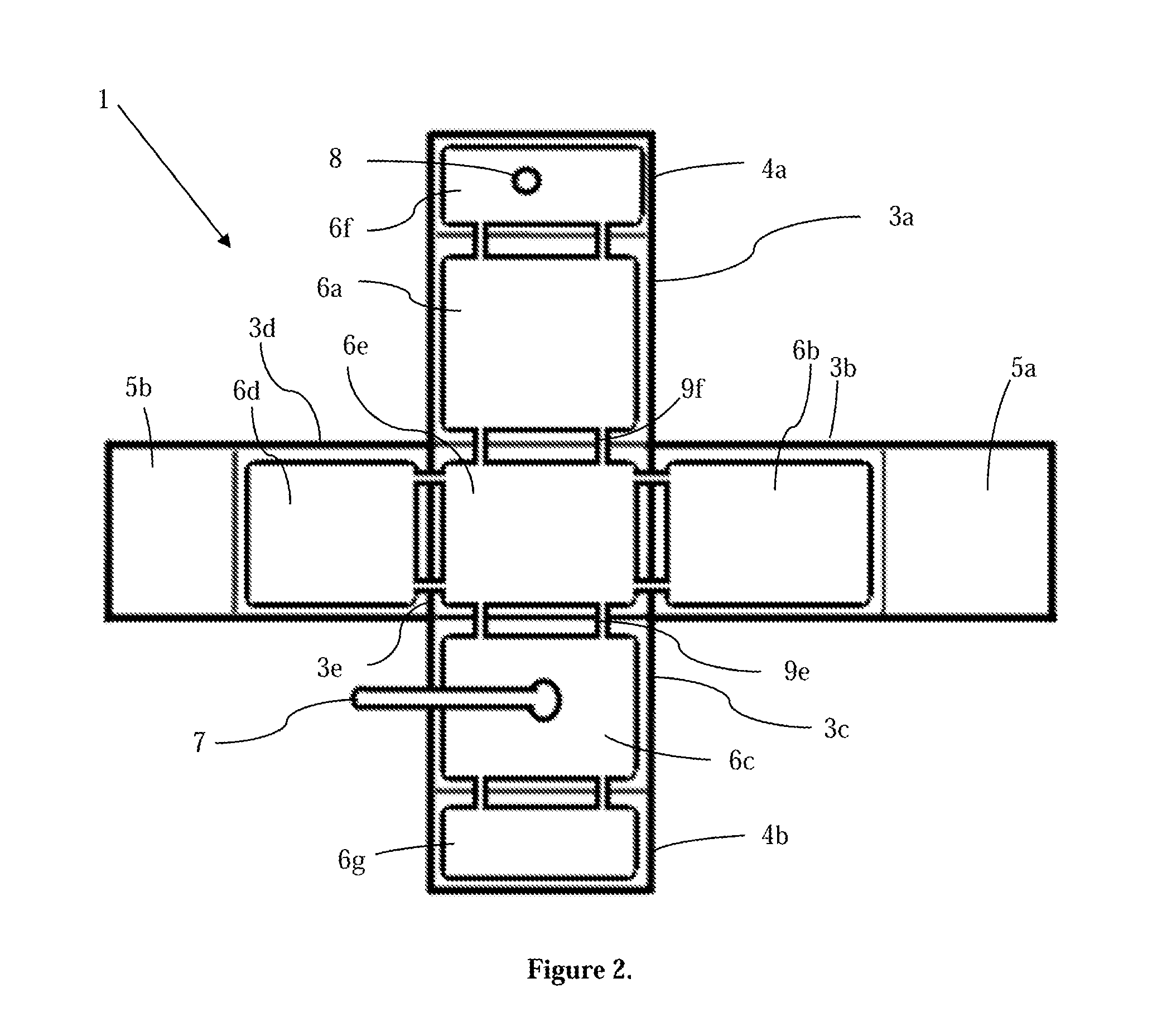
[0028]Inflatable box 1, seen in FIG. 2, is shown as a flat, unassembled box composed of five walls, first wall 3a, second wall 3b, third wall 3c, fourth wall 3d, fifth wall 3e. In addition, top flaps are attached to the walls such that first top flap 4a is attached to first wall 3a and second top flap 4b is attached to third wall 3c. In the example, inflatable box 1 also includes first top overlap panel 5a attached to second wall 3b, and second top overlap panel 5b attached to fourth wall 3d. A plurality of air bladders are attached to the interior wall of the walls and top flaps, with first wall air bladder 6a attached to first wall 3a, second wall air bladder 6b attached to second wall 3b, third wall air bladder 6c attached to third wall 3c, fourth wall air bladder 6d attached to fourth wall 3d, and fifth wall air bladder 6e attached to fifth wall 3e. The top flaps also include air bladders, with sixth air bladder 6f attached to first top flap and seventh air bladder 6g attached t...

example 2

[0031]Valve 7 is in communication with the exterior of inflatable box 1 using tube 30, seen in FIG. 5. Tube 30 is a hollow lumen, long or short tube or tube or tube of any size or shape and may be made of plastic, rubber, or other similar material known in the art. In the present embodiment, valve 7 is connected directly to the interior face of a panel of inflatable box 1 by gluing or otherwise fixing first mounting tab 10 and second mounting tab 11 to the panel face. After assembling inflatable box 1, as seen in FIG. 6, and preparing the box for shipping or storage, gas is applied to tube 30, thereby inflating collapsible inflation tube 15 into a cylinder as described in Example 1 and inflating the air bladders.

example 3

[0032]Valve 7 is connected directly to the exterior face of a panel of inflatable box 1 for inflation of the box. An opening is formed in a panel of inflatable box 1 and collapsible inflation tube 15 is inserted into the opening. First mounting tab 10 and second mounting tab 11 were fixed to the exterior panel face using glue, tape, staples, heat sealing, welding, or other means known in the art.


PUM

PropertyMeasurementUnit
Pressureaaaaaaaaaa
Sizeaaaaaaaaaa
Shapeaaaaaaaaaa

Abstract

An inflatable box or tube container and method of use are disclosed. The inflatable container may be designed in any shape or size and be made up of any rigid material. The box is uniquely designed to allow for a simple one-step process using a box with an integrated inflating tube and bottom liner to expand internally by inflation with a gaseous fluid, thereby three-dimensionally cushioning an article to be shipped. This completely protects the article and removes the need for peanuts, paper or other fillers in boxes used for shipping goods once the box is closed. The box may further include a bleed valve that releases the gaseous fluid if the inflating tube and / or bottom liner are over-inflated.

Description

CROSS-REFERENCE TO RELATED APPLICATIONS[0001]This application is a continuation in part of U.S. patent application Ser. No. 13 / 605,262, Sep. 6, 2012, entitled “Inflatable Box and Method of Use Thereof”, which is a divisional of U.S. patent application Ser. No. 09 / 898,958, filed Jul. 3, 2001, entitled “Inflatable Box”, the contents of which are hereby incorporated by reference.FIELD OF THE INVENTION[0002]This invention relates, generally, to methods of packaging and shipping items. More particularly, it relates to a method of cushioning an item to be shipped.BACKGROUND OF THE INVENTION[0003]The use of different types of packaging for shipping articles is well known. Shipped articles can come in all sizes and shapes. These articles can be fragile or hardy (i.e., the article is considered non-fragile). There are several types and forms of packaging, including peanuts, paper, bubble plastic, foam, etc. However, all of the packaging materials mentioned can cause waste disposal and recycl...

Claims


Application Information

Patent Timeline
IPC IPC(8): B65B5/06B65D81/02
CPCB65B5/06B65D81/02B65D81/052B65B55/20
Inventor SMITH, JACK V.
Owner SMITH JACK V
Learn More