Injection valve for internal combustion engines

a technology for injection valves and internal combustion engines, which is applied in the direction of machines/engines, liquid fuel feeders, mechanical apparatuses, etc., can solve the problems of increasing soot emissions, and achieve the effect of positively modifying the pressure conditions in the hole outlet section and increasing the soot emission in the exhaust gas

Inactive Publication Date: 2014-08-14
ROBERT BOSCH GMBH
View PDF4 Cites 7 Cited by
  • Summary
  • Abstract
  • Description
  • Claims
  • Application Information

AI Technical Summary

Benefits of technology

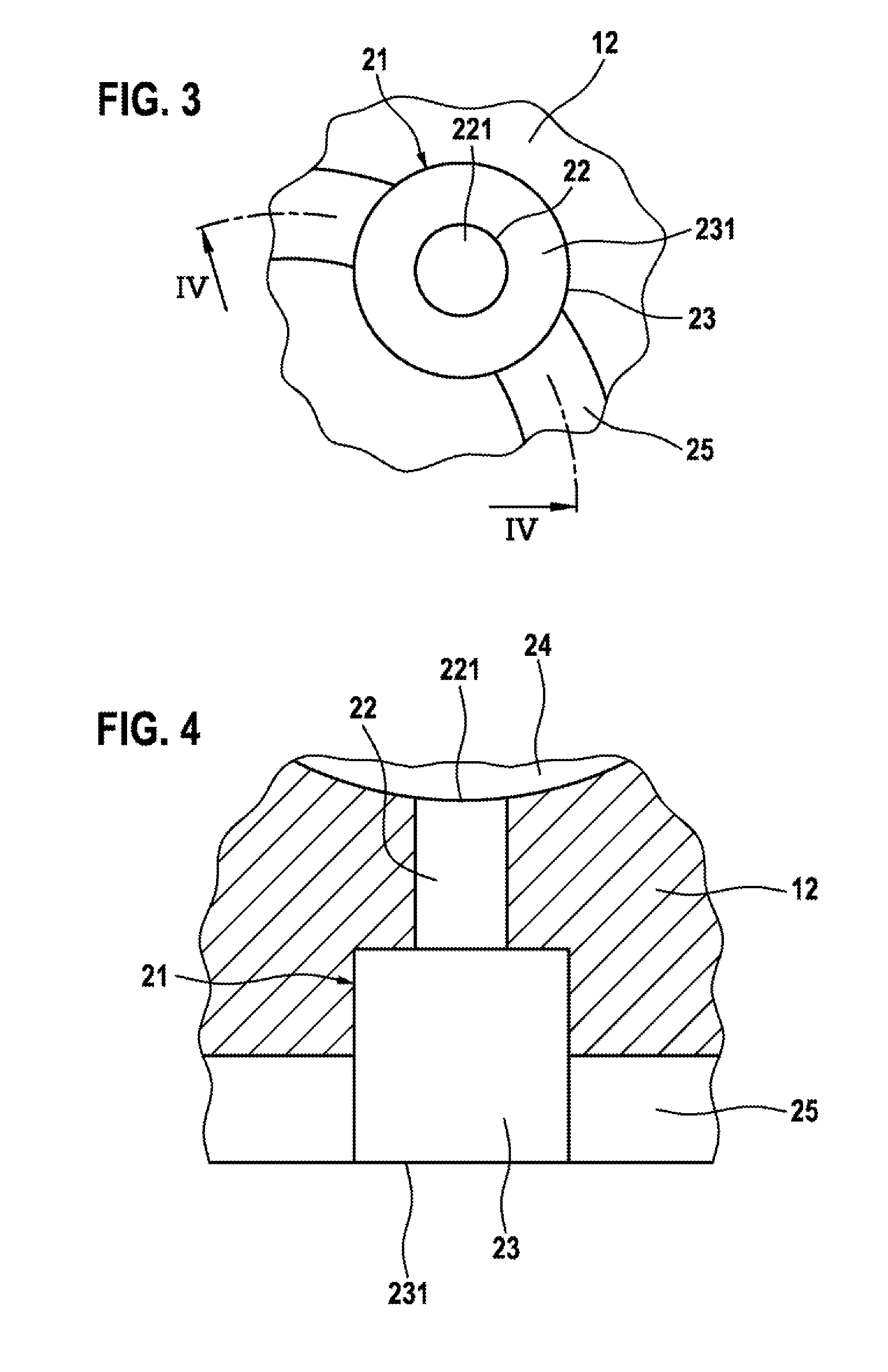
[0004]The injection valve according to the present invention has the advantage that air can flow from outside into the hole outlet sections via the groove that connects all the hole outlet sections of the spray holes, so that adequate ventilation is provided and the pressure conditions in the hole outlet sections are thus positively modified. In the valve closing phase, the exiting wake flow then no longer produces a vacuum that would draw the fuel film, built up during the injection phase on the wall surfaces of the hole outlet sections, in the direction of the hole outlet openings. The exiting of the fuel film from the hole outlet openings is prevented, and the deposits arising due to the engine combustion do not occur at the hole outlet openings—which are critical for nebulization—but rather inside the hole outlet sections, and are therefore no longer relevant to the exhaust gas. In this way, the soot emission of the internal combustion engine can be kept largely constant over its useful life, and the increase in soot emission in the exhaust gas that previously went along with the aging of the engine is avoided.

Problems solved by technology

However, it has turned out that the flow exiting from the spray holes at the end of the injection produces a vacuum region in its wake, due to its inertia, and this vacuum draws the fuel film that builds up on the wall of the hole outlet openings during injection in the direction of the outlet edge of the hole outlet openings.
Due to the poor preparation quality, the latter do not participate adequately in the combustion, causing an increase in soot emissions.

Method used


Image

  • Injection valve for internal combustion engines
  • Injection valve for internal combustion engines
  • Injection valve for internal combustion engines

Examples


Embodiment Construction

[0011]The injection valve of which a part is shown schematically in FIG. 1, with its injecting end shown in longitudinal section, for injecting fuel into a combustion cylinder of an internal combustion engine has a sleeve-type valve seat bearer 11 that extends from a valve housing (not shown here) and is terminated at its free end by a valve seat element 12. On the inner wall, limiting a valve chamber 13, of valve seat element 12 there is fashioned a valve seat 14 in the form of an annular surface that is concentric to the axis of valve seat element 12, and that, together with a closing head 15 of a valve member 16 situated so as to be axially displaceable in valve seat bearer 12, forms a so-called sealing seat. Closing head 15 is fastened, e.g. welded, to the frontal end of a hollow cylindrical valve needle 17 of valve member 16. Valve needle 17 has radial bores 18 and is connected to a fuel supply line (not shown here) that is fashioned in the valve housing, so that fuel moves fro...


PUM


Abstract

An injection valve is indicated for internal combustion engines, having a sealing seat formed by a valve seat and a closing head of a valve needle, and having a plurality of spray holes situated downstream from the sealing seat. The spray holes, which are stepped in cross-section, each have at least one upstream hole inlet section having a very small hole cross-section and a hole inlet opening, and a downstream hole outlet section having a very large hole cross-section and a hole outlet opening. In order to prevent unwanted deposition of burnt fuel on the edges of the hole outlet openings, all the hole outlet sections are connected to one another by a groove having a groove opening that points downstream.

Description

FIELD OF THE INVENTION[0001]The present invention is based on an injection valve for internal combustion engines.BACKGROUND INFORMATION[0002]A known fuel injection valve for internal combustion engines, described in German Published Patent Application No. 10 2005 036 951 and realized as a so-called multi-hole injection valve, has a valve seat element that terminates a hollow cylindrical valve seat bearer and that limits a valve chamber that stands in connection with a fuel supply line. In the valve seating element, there are fashioned a valve seat in the form of an annular surface concentrically surrounding the axis of the valve seat element, and a large number of spray holes. Together with a closing element of a valve member disposed so as to be axially displaceable in the valve seat bearer, the valve seat forms a sealing seat that terminates the spray holes. The valve member is acted on by a valve closing spring that presses the closing head onto the valve seat. An electromagnetic...

Claims


Application Information

Patent Timeline
Patent Type & Authority Applications(United States)
IPC IPC(8): F02M69/04
CPCF02M61/166F02M61/1806F02M61/1846F02M61/188F02M69/04
Inventor VORBACH, MARCO
Owner ROBERT BOSCH GMBH
Why Eureka
Try Eureka