
Pressure sensor arrangement for detecting a pressure of a fluid medium in a measurement area

a technology of pressure sensor and fluid medium, which is applied in the direction of fluid pressure measurement using inductance variation, instruments, manufacturing tools, etc., can solve the problems of difficult to realize the suppression of simultaneous functional dependence of temperature resistance, large pressure range, and large size of the silicon micromechanical system of the sensor element. achieve the effect of large pressure rang

Inactive Publication Date: 2014-08-14
ROBERT BOSCH GMBH
View PDF15 Cites 2 Cited by
  • Summary
  • Abstract
  • Description
  • Claims
  • Application Information

AI Technical Summary

Benefits of technology

The present invention proposes a pressure sensor system that avoids the disadvantages of existing pressure sensors and can be used over a large range of pressures. The sensor element can be passivated, so it does not have any electrical or mechanical attack points for the medium. The pressure sensor system does not require any direct electrical connections or other sensitive components to be sealed, which increases media robustness and temperature resistance compared to existing plastic sensors. The sensor element can also be designed separately or individually for each pressure range, and the evaluation circuit can be placed close to the sensor element to minimize the risk of electrical connection disturbance. The sensor element can be attached to a ceramic using soldering, gluing, or glazing, which further increases media robustness and allows for expanded pressure ranges.

Problems solved by technology

However, it is difficult to realize the suppression of the simultaneous functional dependence of the resistances on temperature and the pressure-tight routing of their electrical terminals out of the pressure medium.
However, high pressures require thicker membranes having a smaller diameter, which for the most part are elastically deflected by only a few micrometers.
Thus, for example the use of the silicon micromechanical system for the sensor element, and protection by an oil reservoir, is relatively expensive and has the disadvantage that the robustness of the sensor system is limited.
Due to the solidity of the standard glass base, however, there is a limitation here due to the burst pressure, so that this pressure sensor system is not suitable for pressures greater than 100 bar.
Such thin membranes are very expensive to shape, and during the connection or assembly process warping can occur, so that a precise pressure measurement is no longer possible.
In these elements, there is in particular the problem of tightness against the medium being measured over the lifespan of the membrane, so that their range of use is limited to approximately 200 bar.
When there is imprecision in the material production, measurement errors therefore occur, and the measurement errors are therefore correspondingly amplified or enlarged, so that as the pressure increases the pressure determination can become more imprecise.
In addition, the electrical signals are very small, so that a large electrical amplification is necessary for processing and output.
In addition, when exposed to the medium such connecting elements can corrode and / or can experience mechanical damage, for example due to the pressure.

Method used


Image

  • Pressure sensor arrangement for detecting a pressure of a fluid medium in a measurement area
  • Pressure sensor arrangement for detecting a pressure of a fluid medium in a measurement area
  • Pressure sensor arrangement for detecting a pressure of a fluid medium in a measurement area

Examples


Embodiment Construction

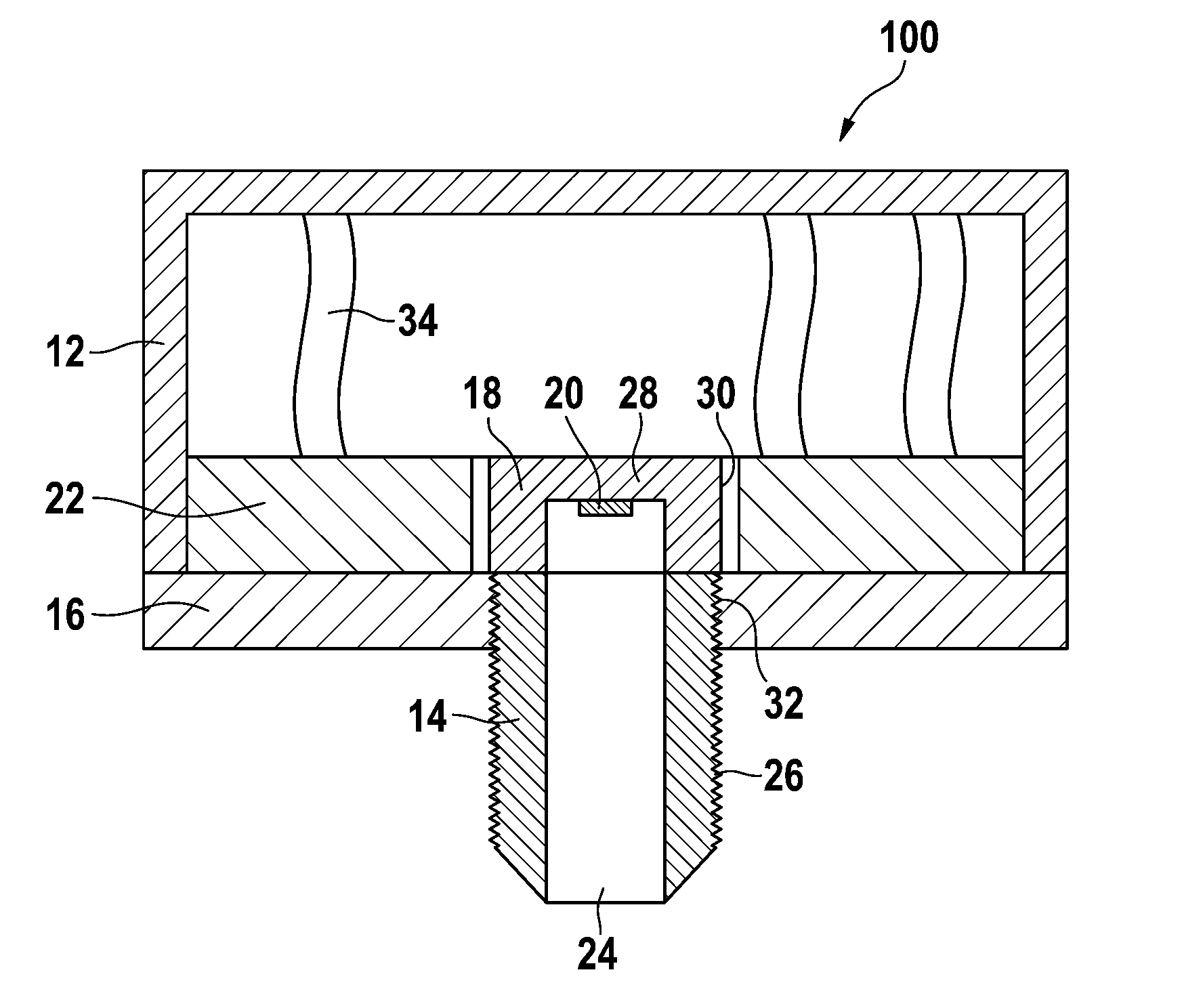
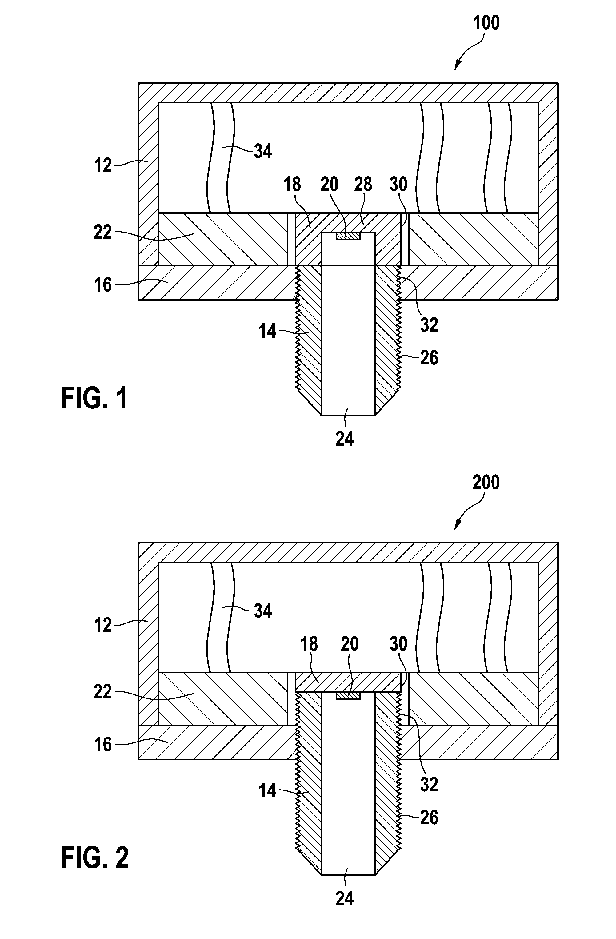
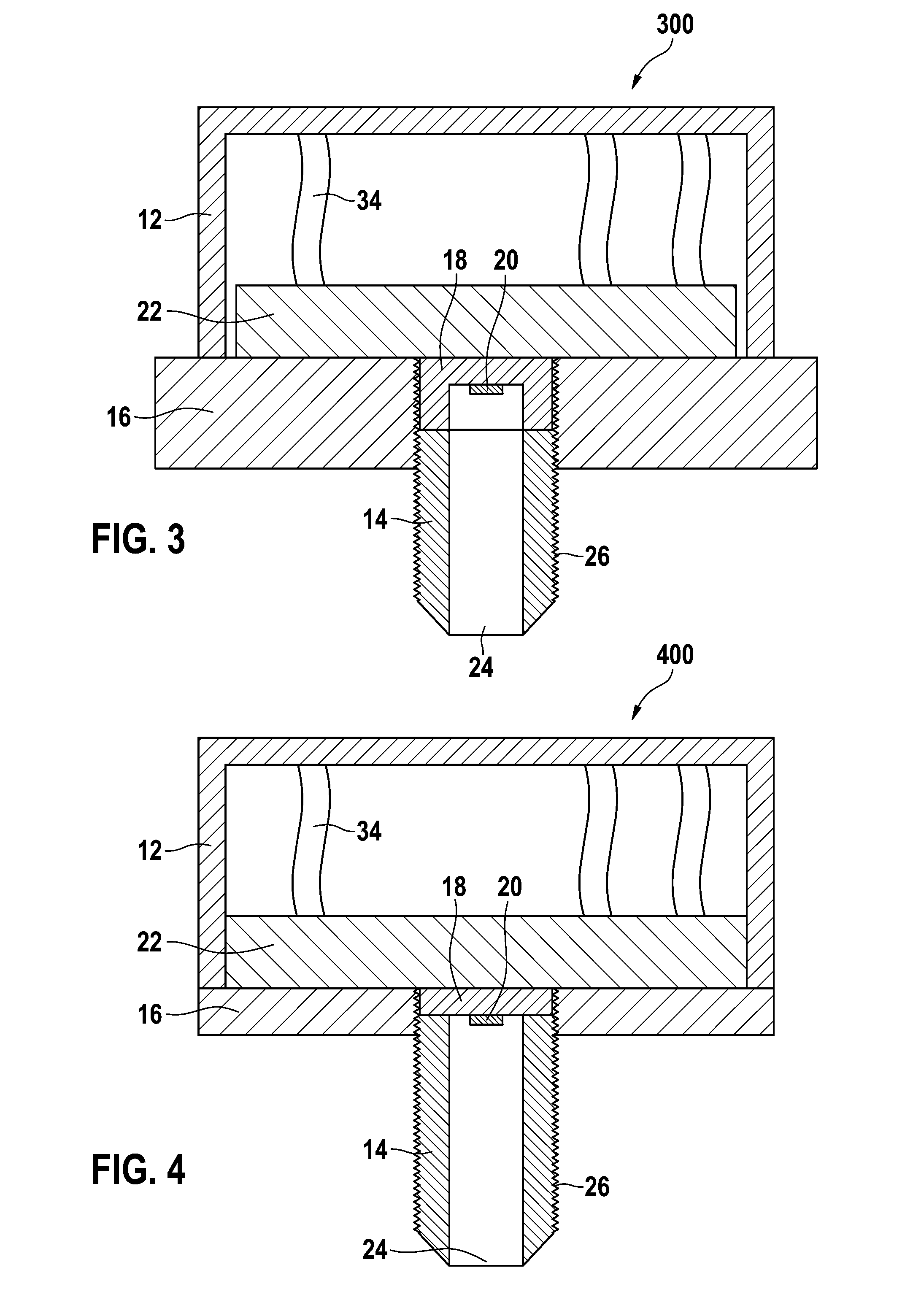
[0045]FIG. 1 shows a first exemplary embodiment of a pressure sensor system 100 according to the present invention. Pressure sensor system 100 includes a sensor housing 12, a pressure connection 14, a housing base 16 having a hexagonal shape, a bearer 18, a sensor element 20, and a circuit board 22 having an evaluation circuit not shown in more detail. Pressure connection 14 is adapted as a threaded connector, and is a substantially cylindrical component that has an opening 24 for the pressurized medium that is to be measured in a measurement chamber (not shown), such as a fuel line, and has an outer threading 26. Bearer 18 is adapted with a cup shape, and is made of a material that is electrically nonconductive but is permeable to a magnetic field. This can be for example a ceramic material. On an inner side of floor area 28 of the cup shape of bearer 18, sensor element 20 is fastened to bearer 18 by soldering, glazing, or gluing. The details of sensor element 20 are described exte...


PUM

PropertyMeasurementUnit
pressuresaaaaaaaaaa
pressuresaaaaaaaaaa
pressuresaaaaaaaaaa

Abstract

A pressure sensor system for acquiring a pressure of a fluid medium in a measurement chamber, and a method for the production thereof, are provided, having a sensor housing, at least one sensor element that is situated on a bearer such that it can be exposed to the medium in order to measure a pressure of the medium, and an evaluation circuit for outputting a signal that indicates the pressure acting on the sensor element. The evaluation circuit is situated outside the medium and is energetically connected to the sensor element in contactless fashion. The bearer is connected to the sensor housing such that the evaluation circuit is situated inside the sensor housing.

Description

CROSS REFERENCE TO RELATED APPLICATION[0001]The present application is the national stage entry of International Patent Application No. PCT / EP2012 / 057745, filed on Apr. 27, 2012, which claims priority to Application No. DE 10 2011 077 868.3, filed in the Federal Republic of Germany on Jun. 21, 2011.BACKGROUND INFORMATION[0002]From the existing art, various devices and methods are known for acquiring pressures of fluid media, such as gases and liquids. Pressure, as a measurement quantity, is a non-directional force action that occurs in gases and liquids and that acts at all sides. Dynamically acting and statically acting measurement value recording elements, or sensors, are used to measure pressures. Dynamically acting pressure sensors are used only to measure pressure fluctuations in gaseous or liquid media. The pressure measurement can take place directly, via membrane deformation, or via a force sensor.[0003]In particular for the measurement of very high pressures, it would be ad...

Claims


Application Information

Patent Timeline
Patent Type & Authority Applications(United States)
IPC IPC(8): G01L9/00
CPCG01L19/086G01L19/148G01L19/149G01L9/0041G01L11/00Y10T29/49826
Inventor LUX, ALEXANDERMAST, MARTIN
Owner ROBERT BOSCH GMBH
Learn More