Outboard motor control apparatus

a technology for controlling apparatus and motors, applied in marine propulsion, vessel construction, propulsion transmission, etc., can solve the problems of not always best to shift down and scarce cavitation, and achieve the effect of suppressing cavitation and facilitating smooth turning of boats

Active Publication Date: 2014-08-07
HONDA MOTOR CO LTD
View PDF2 Cites 4 Cited by
  • Summary
  • Abstract
  • Description
  • Claims
  • Application Information

AI Technical Summary

Benefits of technology

[0005]Therefore, embodiments of the invention are directed to overcoming the foregoing problems by providing a control apparatus for a boat installed with outboard motors that effectively suppresses occurrence of cavitation to facilitate smooth turning of the boat by selecting gear of the transmission based on a slip ratio of the propeller when the rudder angle is relatively large.

Problems solved by technology

However, since occurrence of cavitation at turning of the boat differs according to the operating conditions of an engine or the transmission, or the specifications of the propeller, and the like, cavitation scarcely occurs depending on conditions even with a relatively large rudder angle.
Therefore, it is not always best to shift down only based on the rudder angle without exception.

Method used


Image

  • Outboard motor control apparatus
  • Outboard motor control apparatus
  • Outboard motor control apparatus

Examples


first embodiment

[0026]An outboard motor control apparatus according to the invention will now be explained with reference to the attached drawings.

third embodiment

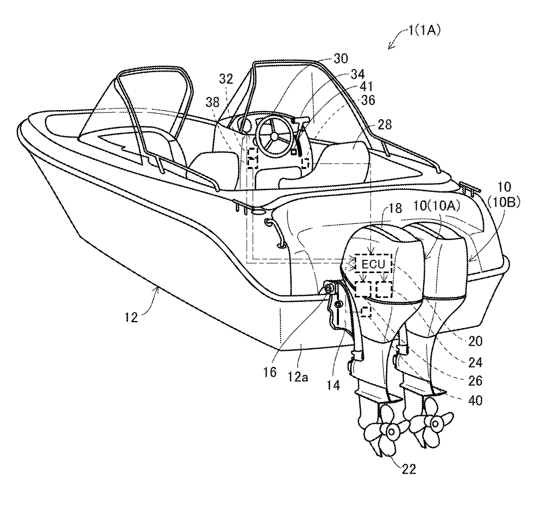
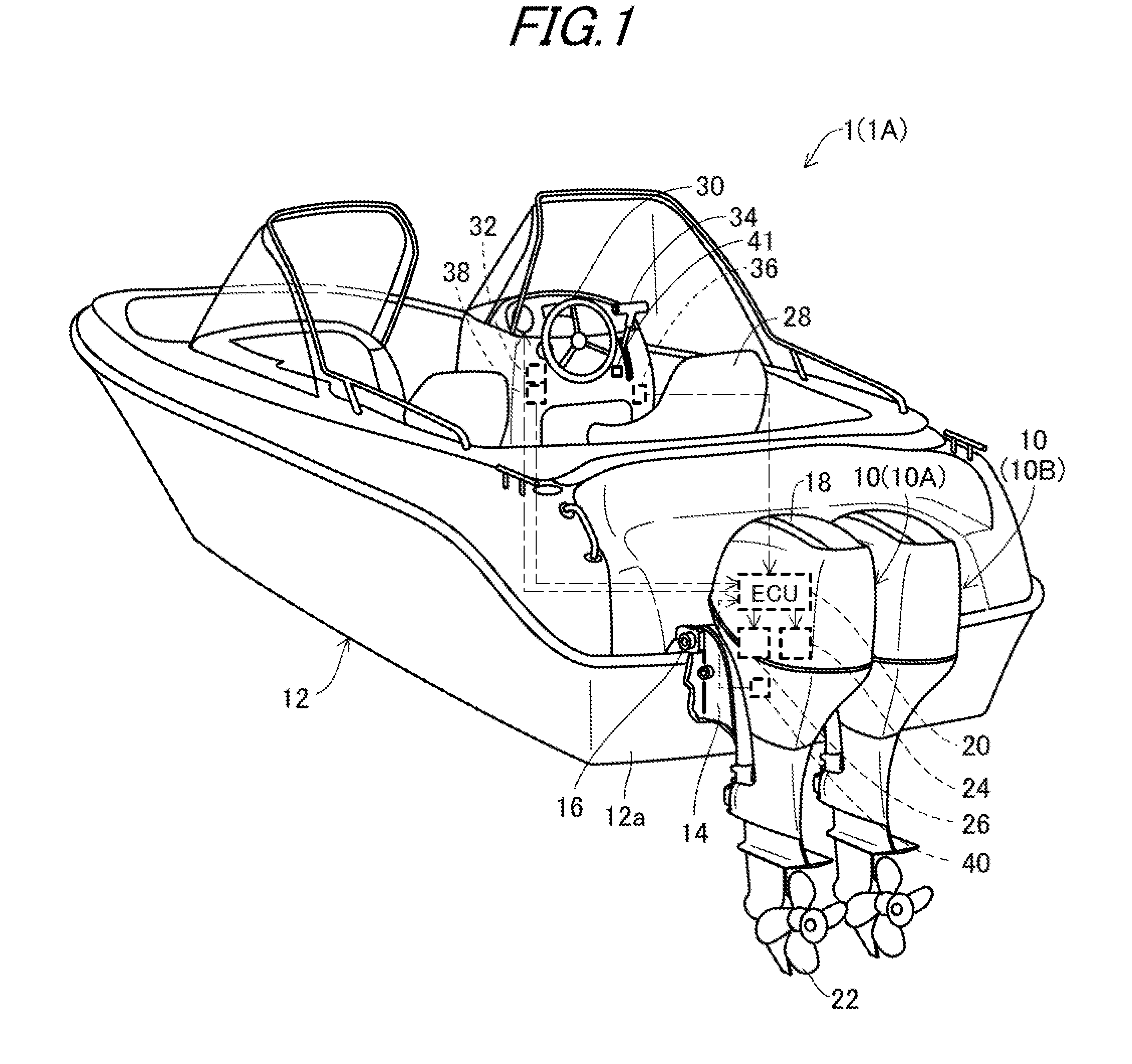
[0027]FIG. 1 is an overall schematic view of outboard motors installed on a boat according to the first and a

[0028]In FIG. 1, symbol 1A indicates a boat 1A whose hull 12 is mounted with a plurality of outboard motors 10 side by side, specifically two outboard motors comprising an outboard motor 10A installed at the port side (left-hand side as the operator faces forward toward the bow; hereinafter referred to as “first outboard motor”), and an outboard motor 10B installed at the starboard side (right-hand side in that direction; hereinafter referred to as “second outboard motor”). Since the first and second outboard motors 10A and 10B have the same structure, they will generally be explained in the following as the outboard motors 10, unless otherwise mentioned.

[0029]As illustrated, the outboard motor 10 (10A) is clamped (fastened) to the stern or transom 12a of the hull 12, through stern brackets 14 and a tilting shaft 16.

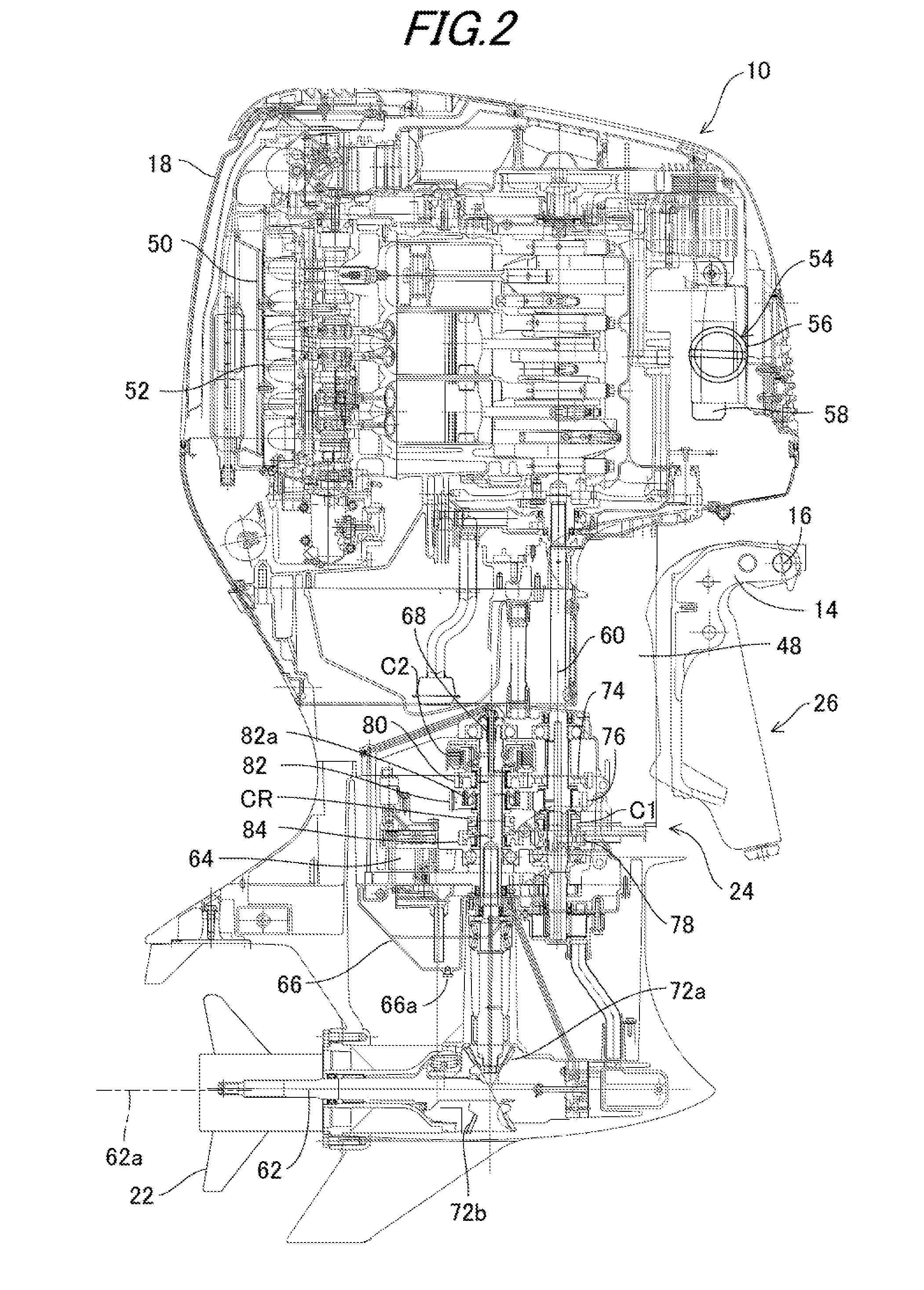
[0030]The outboard motor 10 has an internal combustion engin...

second embodiment

[0144]Next, an outboard motor control apparatus according to the invention will now be explained.

[0145]The second embodiment will be explained with focus on the points of difference from the first embodiment. With a boat installed with a plurality of outboard motors, especially three or more outboard motors, it is difficult to achieve smooth turning by only controlling transmissions of respective outboard motors equally.

[0146]Therefore, the outboard motor control apparatus according to the second embodiment of the invention is configured to suppress cavitation arising from turning effectively, and to make smooth turning even with the boat installed with three outboard motors or more.

[0147]FIG. 11 is an overall schematic view of outboard motors installed on a boat to which an outboard motor control apparatus according to a second embodiment of the invention is applied.

[0148]In FIG. 11, symbol 1B indicates the boat whose hull 12 is mounted with a plurality of outboard motors 10 side b...


PUM


Abstract

A control apparatus for an outboard motor mounted on a boat and equipped with a transmission having at least forward first and second speed gears and a reverse gear. The apparatus functions as a rudder angle detector that detects a rudder angle, a slip ratio detector that detects a slip ratio, and a transmission controller. The transmission controller controls the operation of the transmission to select one of the gears based on the detected engine speed or the detected slip ratio according to a comparison between the detected rudder angle and a predetermined angle.

Description

TECHNICAL FIELD[0001]Embodiments of the invention generally relate to an outboard motor control apparatus, more particularly to a control apparatus for a plurality of outboard motors installed on a boat and each equipped with a transmission.RELATED ART[0002]With reference to a boat installed with an outboard motor equipped with a transmission, there has been proposed a technique to suppress cavitation occurring around a propeller when the boat is steered to turn so as to turn the boat smoothly, for example, by U.S. Pat. No. 8,444,446 filed and patented claiming the priority of Japanese Laid-Open Patent Application No. 2011-183903.[0003]In the reference, the operation of the transmission is controlled to change the gear position from a second speed to a first speed when detected throttle change amount not less than a first predetermined value and operation of the trim angle regulation mechanism is controlled to start the trim-up operation such that the trim angle converges to a prede...

Claims


Application Information

Patent Timeline
Patent Type & Authority Applications(United States)
IPC IPC(8): B63H21/21
CPCB63H21/21B63H20/12B63H2020/003
Inventor KURIYAGAWA, KOJIYOSHIMURA, HAJIME
Owner HONDA MOTOR CO LTD
Why Eureka
Try Eureka