
Power generation apparatus and ship propelling apparatus including buoyancy body as well as web-structured wing portions provided thereto

a technology of power generation apparatus and propelling apparatus, which is applied in the direction of renewable energy generation, vessel construction, greenhouse gas reduction, etc., can solve the problems of low power generation efficiency, excessive installation space, and solar power generation, and achieves high efficiency, convenient installation, and convenient implementation.

Inactive Publication Date: 2014-08-07
LEE SEONG WOO
View PDF10 Cites 5 Cited by
  • Summary
  • Abstract
  • Description
  • Claims
  • Application Information

AI Technical Summary

Benefits of technology

The present invention provides a power generation apparatus that can be easily installed on or below the water surface using buoyancy, and has advantages such as high efficiency, low installation costs, and eco-friendliness. Additionally, the apparatus can generate stable electricity regardless of wind or weather changes, and actively adapt to changes in water or wind velocity. Furthermore, the apparatus is durable, easily enlarged, and can be easily mounted on a single ship in multiple number to increase propulsion velocity. The technical effects of the invention are stable power generation and efficient propulsion.

Problems solved by technology

Considering the key point, solar power generation has disadvantages that require an excessive installation space and have extremely low power generation efficiency until now.
And wind power generation also has disadvantages that require a large installation space, have a difficulty in enlargement, and have to consider natural environment conditions excessively.
In addition, tidal current power generation using the flow of a tide has a limit to enlargement, because a tidal current power generation apparatus is required to be installed in an area having a fast current, and although having an advantage that is enlarged easier than wind power and tidal current power generation, tidal power generation that uses potential energy of sea level caused by a tidal phenomenon to generate electricity also has other disadvantages that spend a large amount of costs to build a huge sea wall and causes environmental destruction.
The propelling apparatus is typically made out of metals, thereby becoming heavy, and therefore has disadvantages that consume a large amount of energy when being driven as well as have a difficulty in using max performance because of a cavitation phenomenon.

Method used


Image

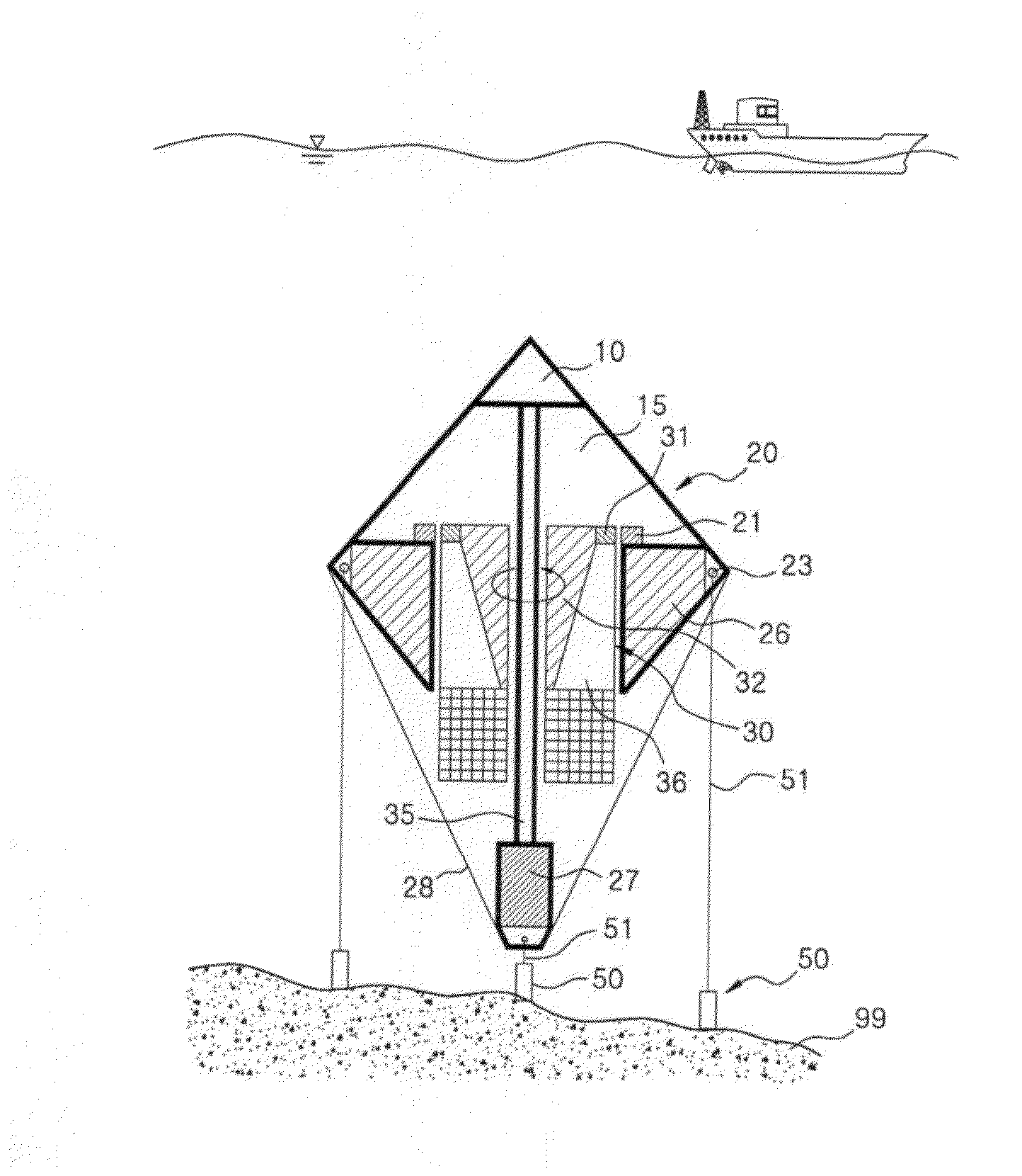
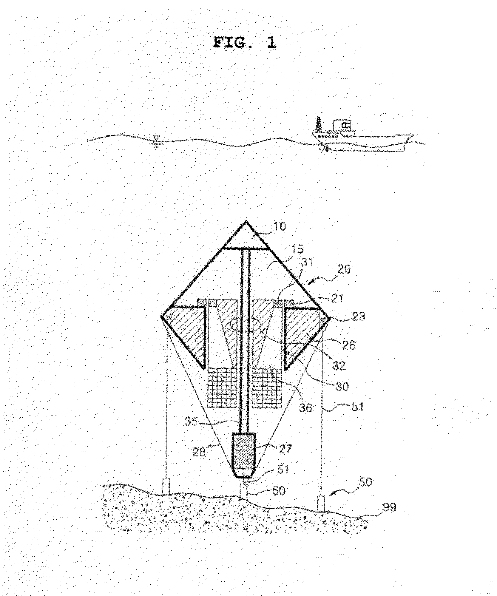
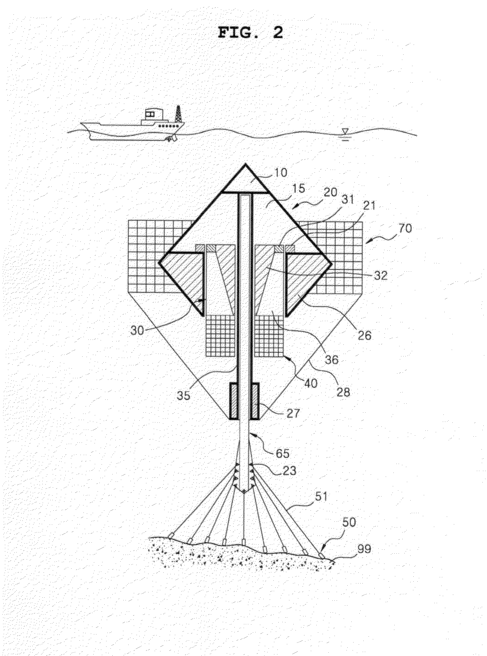
  • Power generation apparatus and ship propelling apparatus including buoyancy body as well as web-structured wing portions provided thereto
  • Power generation apparatus and ship propelling apparatus including buoyancy body as well as web-structured wing portions provided thereto
  • Power generation apparatus and ship propelling apparatus including buoyancy body as well as web-structured wing portions provided thereto

Examples


second embodiment

[0057]According to the present invention, the power generation apparatus with such a configuration generates electricity in such a manner that the first wing portion 30 mounted on the rotary body 30 and the second wing portion 70 mounted on the submersible buoyancy body 20 are rotated in the opposite direction to each other. Configurations of she wing portions 40 and 70 that may be mounted on the power generation apparatus according to the present invention as well as the principle that the wing portions 40 and 70 are rotated in the opposite direction to each other are described below.

[0058]FIG. 3 illustrates an exemplary wing portion including multiple wing support frames, FIG. 4 illustrates a state in which wings made out of a material that is flexible to be foldable and rollable and blocks the penetration of a liquid or a gas are pivotably connected to a wing frame according to the present invention in a schematic view, FIG. 5 illustrates an operation principle or the wings shown...

fifth embodiment

[0075]Referring to FIG. 10, the power generation apparatus according to the present invention includes a buoyancy body extension shaft 35 provided inside the center of a submersible buoyancy body 20, and the buoyancy body extension shaft 35 is formed in a shape that is hollow inside and has the other open end. Also, a central shaft 38 is provided to the center of one end of a rotary body 30, and the central shaft 38 is inserted into the buoyancy body extension 35 shaft through an opening on the other end of the buoyancy body extension shaft, thereby being rotatably connected to the extension shaft.

[0076]In the power generation apparatus with such a configuration according to the fourth and fifth embodiments of the present invention, the first wing portion 40 is rotated by a tidal current in a state in which a part of the submersible buoyancy body 20 is exposed above the sea level and the rotary body 30 as well as the first wing portion mounted on the rotary body 30 are submerged bel...

seventh embodiment

[0084]In another power generation apparatus according to the present invention, it is possible to fill a lower portion of the submersible buoyancy body with water and then float the rotary body 30 consisting of the buoyancy bodies 32 and 36 over the water surface rather than to provide the first ballast tank 26 to the lower portion of the submersible buoyancy body 20 as described above. Here, the rotor 31 is provided to an edge of the rotary body 30.

[0085]Reference numeral 56 represents a rotor support wire which is used to securely fix the rotor support 55 and the rotor 31. Referring to FIG. 13, another configuration according to the seventh embodiment of the present invention is identical to the above-mentioned configuration according to the seventh embodiment of the present invention except that the power generation means mounted on the top of the first ballast tank 26 may be provided to the lower portion of the central shaft 38. Here, the power generation means may include a gen...


PUM


Abstract

The present invention relates to various types of power generation apparatuses and ship propelling apparatuses including a buoyancy body as well as wing portions thereto, which include wing frames with a multistage, lattice web structure foldable and rollable wings which are connected to the wing frames, wherein the power generation apparatus includes a submersible buoyancy body which has one closed end and the other open end as well as a buoyancy space formed therein, a rotary body which is rotatably connected inside the submersible buoyancy body and has a first wing portion mounted on the other end thereof, and a power generation means which is disposed between the submersible buoyancy body and the rotary body to generate electricity.

Description

TECHNICAL FIELD [0001]The present invention relates to a power generation apparatus and a ship propelling apparatus including a buoyancy body as well as web-structured wing portions provided thereto, especially to a power generation apparatus which includes a buoyancy body and generates electricity using a horizontal flow force of a liquid or a gas and a ship propelling apparatus which propels a ship as well as web-structured wing portions that may be provided thereto.BACKGROUND ART [0002]As fossil fuels have been excessively used, environmental pollution gradually becomes worse, and consequently more attention has been drawn to eco-friendly energy today. Especially, because fossil fuel prices have been skyrocketing recently, many researches have been developed that use solar, wind, or tidal power to generate electricity. The key point in generating eco-friendly energy by using natural power is to enlarge a power generation unit to improve generation efficiency.[0003]Considering the...

Claims


Application Information

Patent Timeline
Patent Type & Authority Applications(United States)
IPC IPC(8): F03B17/06
CPCF03B17/062F03B13/10F03B13/264F03B17/02F03B17/06F03B17/065F03D3/067F05B2210/18F05B2240/917F05B2240/93F05B2240/931F05B2240/932F05B2240/95F05B2240/97Y02E10/30Y02E10/727Y02E10/74Y02T70/5236Y02E10/20Y02E10/728
Inventor LEE, SEONG-WOO
Owner LEE SEONG WOO
Learn More