
Touch panel assembly and electronic apparatus

a technology of electronic equipment and touch panel, which is applied in the direction of instruments, computing, electric digital data processing, etc., to achieve the effect of reducing the size of the touch panel and reducing the manufacturing cos

Inactive Publication Date: 2014-08-07
HTC CORP
View PDF4 Cites 13 Cited by
  • Summary
  • Abstract
  • Description
  • Claims
  • Application Information

AI Technical Summary

Benefits of technology

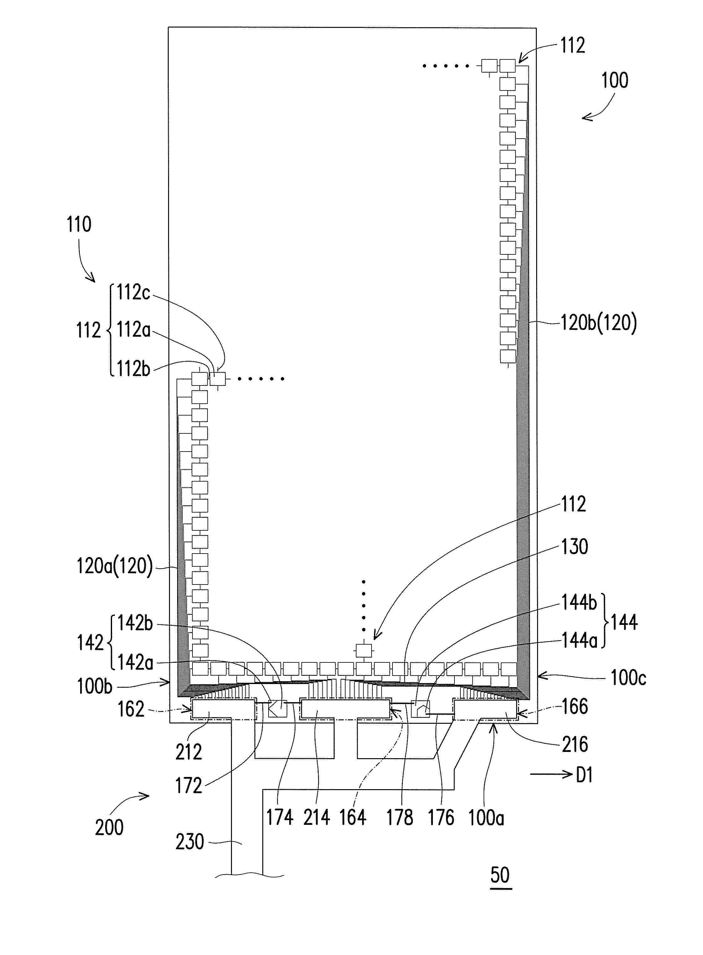
The present patent application is directed to a touch panel assembly that efficiently uses the layout space and reduces the size of the touch panel while lowering manufacturing costs. Pads are placed on both sides of input elements, and a flexible circuit board is extended and bonded with the pads. This compact circuit layout enables a smaller touch panel size and lower manufacturing costs. Additionally, utilizing the touch panel assembly expands the available space inside an electronic device, reduces the surrounding border, and increases the display area.

Problems solved by technology

However, peripheral circuits of the touch panel or wires for connecting the electrodes take up layout space on the touch panel.

Method used


Image

  • Touch panel assembly and electronic apparatus
  • Touch panel assembly and electronic apparatus
  • Touch panel assembly and electronic apparatus

Examples


Embodiment Construction

[0032]Reference will now be made in detail to the present preferred embodiments of the application, examples of which are illustrated in the accompanying drawings. Wherever possible, the same reference numbers are used in the drawings and the description to refer to the same or like parts.

[0033]The design provided by the application is suitable for an electronic apparatus, such as a mobile phone, a tablet PC, or an eBook. Following embodiments will be described by taking a mobile phone as an example.

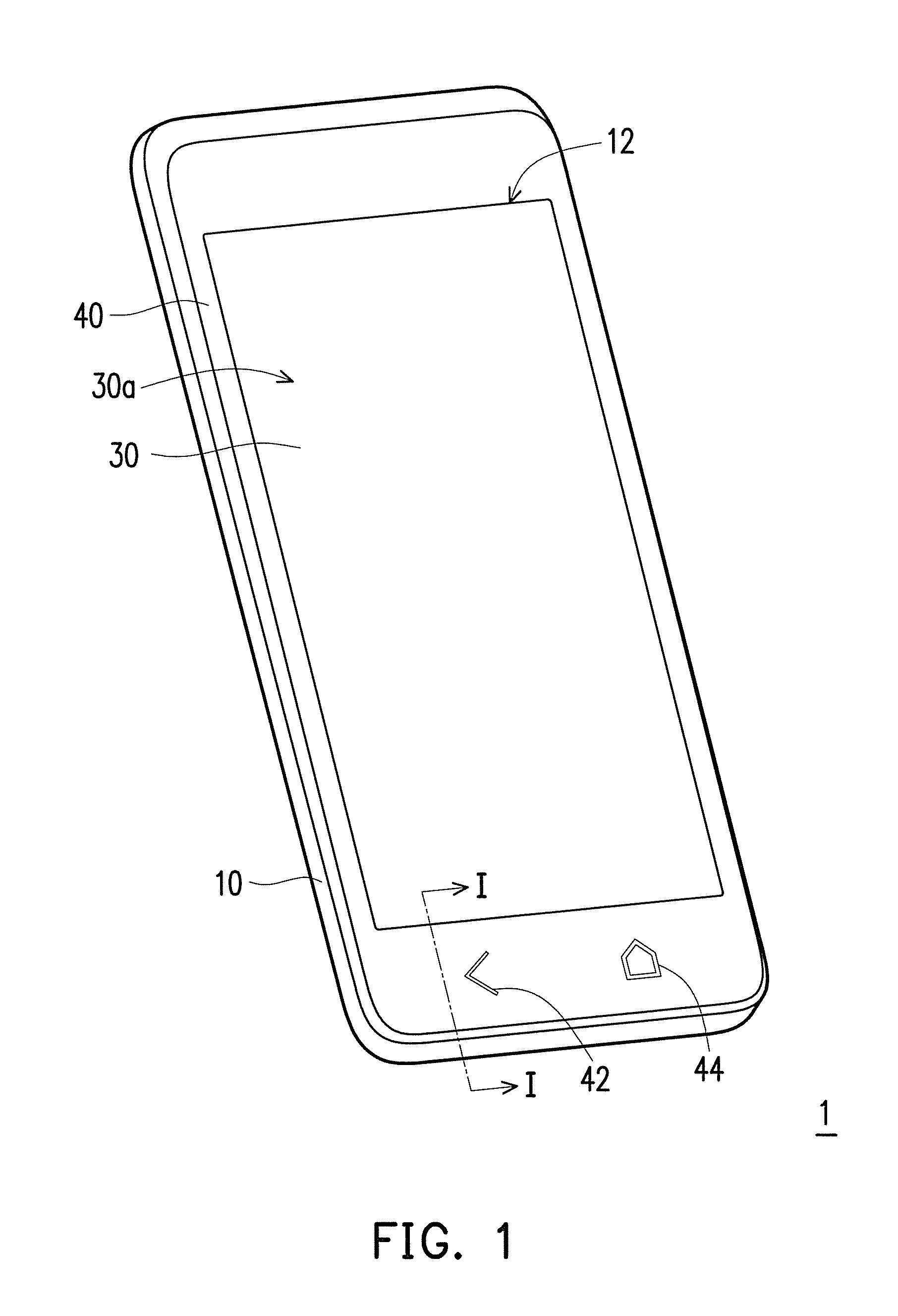
[0034]FIG. 1 is a perspective view of an electronic apparatus according to an embodiment of the application. FIG. 2 is a partial cross-sectional view of the electronic apparatus of FIG. 1 along line I-I. Referring to FIG. 1 and FIG. 2, the electronic apparatus 1 in the present embodiment includes a casing 10, a main module 20, a display module 30, a touch panel 100, a flexible circuit board 200, and a transparent cover 40. The casing 10 has an opening 12. The main module 20 is disposed i...


PUM

PropertyMeasurementUnit
flexibleaaaaaaaaaa
transparentaaaaaaaaaa
timeaaaaaaaaaa

Abstract

A touch panel assembly includes a touch panel and a flexible circuit board. The touch panel includes a sensing array having sensing units, first connection lines, second connection lines, at least one input element, and pads. The first and second connection lines are outside the sensing array and electrically connected to the sensing units respectively. The input element is outside the sensing array and close to a side of the touch panel. The pads are in a bonding region of the touch panel and electrically connected to the first and second connection lines respectively. The bonding region is close to the side of the touch panel and is arranged along with the input element in parallel to the side of the touch panel. The flexible circuit board has a connecting portion extended and attached to the bonding region. Terminals of the connecting portion are electrically connected to the pads respectively.

Description

BACKGROUND OF THE APPLICATION[0001]1. Field of the Application[0002]The present application generally relates to a touch panel assembly and an electronic apparatus, and more particularly, to a capacitive touch panel assembly and an electronic apparatus using the same.[0003]2. Description of Related Art[0004]Along with the rapid development and widespread of information technology, wireless mobile communications, and information appliance in recent years, the conventional input devices (for example, keyboards and mouses) of many information products have been replaced by touch panels in order to provide a more convenient, light-weighted, and intuitional experience to the users.[0005]Touch panels can be categorized into resistive touch panels, capacitive touch panels, optical touch panels, acoustic wave touch panels, and electromagnetic touch panels according to the touch-sensing techniques adopted by these touch panels. Compared to other types of touch panels, capacitive touch panels...

Claims


Application Information

Patent Timeline
Patent Type & Authority Applications(United States)
IPC IPC(8): G02F1/1333
CPCG02F1/13338G06F3/04164G06F3/041G06F3/045
Inventor CHUANG, I-CHENGCHIEN, SHIH-POLIU, YI-TINGPENG, CHIA-HSIUNGWANG, CHI-JER
Owner HTC CORP
Learn More