
Radiation imaging system and control method thereof, and radiation image detecting device

a technology of radiation imaging and control method, applied in the direction of radiation diagnostic device control, application, instruments, etc., can solve the problems of increasing the affecting the timing of starting the x-ray emission, and affecting the timing of the start of the x-ray emission, so as to prevent the delay of the stop signal, reduce unnecessary radiation exposure of the object, and stop the radiation emission

Active Publication Date: 2014-07-31
FUJIFILM CORP
View PDF2 Cites 12 Cited by
  • Summary
  • Abstract
  • Description
  • Claims
  • Application Information

AI Technical Summary

Benefits of technology

The present invention relates to a radiation imaging system and control method that can prevent delays in stopping the emission of radiation from the source. This is achieved by regulating the communication of signals other than the stop signal and allowing the image detector to perform the accumulation operation at least until the stop signal is transmitted. This system can reduce unnecessary radiation exposure of the object, prevent excessive dose application and degradation in the quality of the radiographic image.

Problems solved by technology

Thus, using the photo timer in the AEC requires an X-ray dose to be increased by an X-ray absorption amount by the photo timer, and hence causes increase in radiation exposure of the object.
In the communication among the essential devices of the X-ray imaging system, e.g. between the X-ray image detecting device and the console and between the X-ray image detecting device and the X-ray generating apparatus, communications line congestion and signal collision cause the occurrence of a communication delay.
The larger the communication delay, the more the timing of starting the X-ray emission is delayed.
At the worst, such a situation may occur that the X-ray generating apparatus keeps emitting the X-rays even after the X-ray image detecting device completes the image accumulation operation.
This is because a delay occurring in the stop signal prevents the X-ray emission from stopping at an appropriate time, and therefore brings about increase in the radiation exposure of the object.
The delay in stopping the X-ray emission also causes application of the X-rays beyond a target dose, and hence results in deterioration in the quality of the X-ray image.
Elongating the image accumulation time in anticipation of the communication delay cannot solve the communication delay in the stop signal, as a matter of course.
Thus, adopting this unidirectional communications is unrealistic.

Method used


Image

  • Radiation imaging system and control method thereof, and radiation image detecting device
  • Radiation imaging system and control method thereof, and radiation image detecting device
  • Radiation imaging system and control method thereof, and radiation image detecting device

Examples


Embodiment Construction

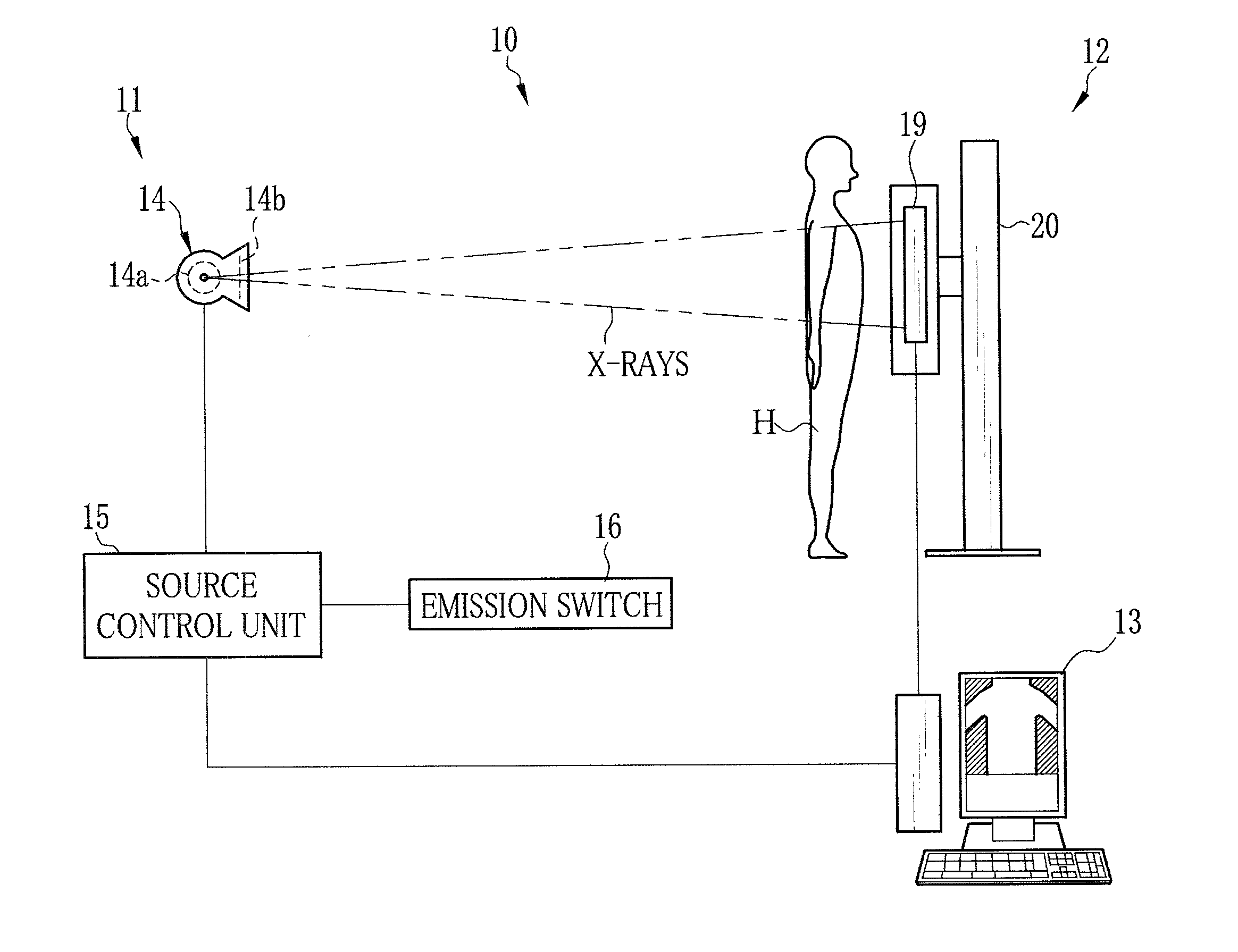
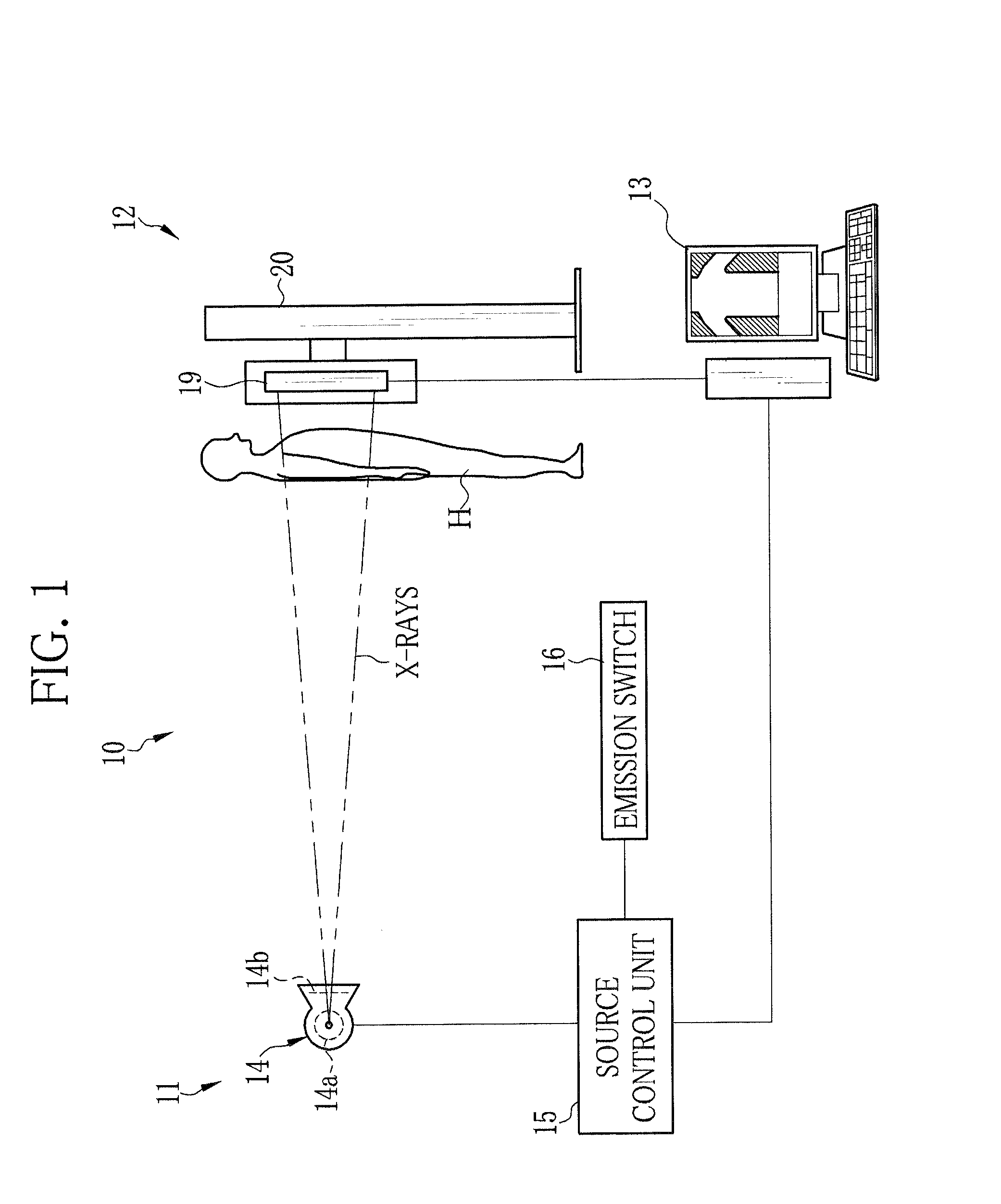
[0035]In FIG. 1, an X-ray imaging system 10 is constituted of an X-ray generating apparatus 11, an X-ray imaging apparatus 12, and a console 13. The X-ray generating apparatus 11 includes an X-ray source 14, a source control unit 15 for controlling the X-ray source 14, and an emission switch 16. The X-ray source 14 has an X-ray tube 14a for radiating X-rays and an irradiation field limiter (collimator) 14b for limiting an irradiation field of the X-rays radiating from the X-ray tube 14a.

[0036]The X-ray tube 14a has a cathode composed of a filament for emitting thermoelectrons, and an anode (target) that radiates the X-rays by collision of the thermoelectrons emitted from the cathode. The irradiation field limiter is composed of, for example, four lead plates for blocking the X-rays. The four lead plates are disposed in each side of a rectangle so as to form a rectangular irradiation opening in a middle to pass the X-rays therethrough. Shifting the position of the lead plates varies...


PUM


Abstract

Upon input of a synchronization signal, which indicates a start of an X-ray emission, from a source control unit for controlling an X-ray source, an electronic cassette makes an FPD start an accumulation operation and measurement of an X-ray dose. The electronic cassette and a console command their communicators to stop communication of any signal other than a stop signal, which stops the X-ray emission from the X-ray source, during the accumulation operation of the FPD. As soon as the X-ray dose has reached a predetermined threshold value, the electronic cassette transmits the stop signal to the source control unit through the console. A delay in transmission of the stop signal due to communication congestion or signal collision does not occur, because the electronic cassette and the console stop the communication of the signal other than the stop signal.

Description

BACKGROUND OF THE INVENTION[0001]1. Field of the Invention[0002]The present invention relates to a radiation imaging system for imaging a radiographic image of an object and a control method thereof, and a radiation image detecting device used in the radiation imaging system.[0003]2. Description Related to the Prior Art[0004]In a medical field, an X-ray imaging system using X-rays, for example as a kind of radiation, is known. The X-ray imaging system is constituted of an X-ray generating apparatus for applying the X-rays to an object and an X-ray image detecting device, which receives the X-rays passed through the object and detects an X-ray image representing image information of the object. In the X-ray image detecting device, an X-ray film, an imaging plate (IP), or the like is conventionally used as a detection panel. However, an X-ray image detecting device using a flat panel detector (FPD) as the detection panel has become widespread presently. The FPD has a matrix of pixels ...

Claims


Application Information

Patent Timeline
Patent Type & Authority Applications(United States)
IPC IPC(8): A61B6/00
CPCA61B6/542A61B6/4233A61B6/4283A61B6/54A61B6/56A61B6/585G03B42/02
Inventor KUWABARA, TAKESHIKAMIYA, TAKESHIKITAGAWA, YUSUKETAJIMA, TAKASHI
Owner FUJIFILM CORP
Learn More