Controlling method and system based on the automotive lighting system illumination angle synchronizing with the automotive speed

a technology of lighting system and control method, which is applied in the direction of vehicle components, signalling/lighting devices, optical signalling, etc., can solve the problems of inconvenient use, no synchronizing ability, and inability to meet the drivers with dynamic perspective synchronizing with speed on demand, so as to improve driving safety

Inactive Publication Date: 2014-07-31
SHENZHEN PROTRULY ELECTRONICS CO LTD
View PDF22 Cites 1 Cited by
  • Summary
  • Abstract
  • Description
  • Claims
  • Application Information

AI Technical Summary

Benefits of technology

The present invention provides a controlling method and an application system based on the automotive lighting system illumination angle synchronizing with the automotive speed. The technical effects of this invention are as follows: synchronizing the illumination angle with the automotive speed improves driving safety and provides convenience to users, automatically adjusting the angles of lighting apparatus under different automotive speeds to broaden the driver's viewing range and make the distant road clearly seeable at a high speed to find the dangers ahead, and saving the power when the automobiles is in a low speed driving condition to make up the weakness that human vision worsens due to physiological responses caused by attention concentrations in a high speed driving condition.

Problems solved by technology

In the existing automotive lighting systems, both horizontal concentration angle and vertical concentration angle can be manually adjusted, but it is fixed during driving, thus it can't meet the drivers with dynamic perspective synchronizing with speed on demand.
The automotive lighting system of the prior art has no synchronizing ability between the viewing angle and the automotive speed, which is sometimes inconvenient for users.

Method used


Image

  • Controlling method and system based on the automotive lighting system illumination angle synchronizing with the automotive speed
  • Controlling method and system based on the automotive lighting system illumination angle synchronizing with the automotive speed
  • Controlling method and system based on the automotive lighting system illumination angle synchronizing with the automotive speed

Examples


Embodiment Construction

[0057]In order to make the purpose, technical solution and the advantages of the present invention clearer and more explicit, further detailed descriptions of the present invention is stated here, referencing to the attached drawings and some embodiments of the present invention. It should be understood that the detailed embodiments of the invention described here are used to explain the present invention only, instead of limiting the present invention.

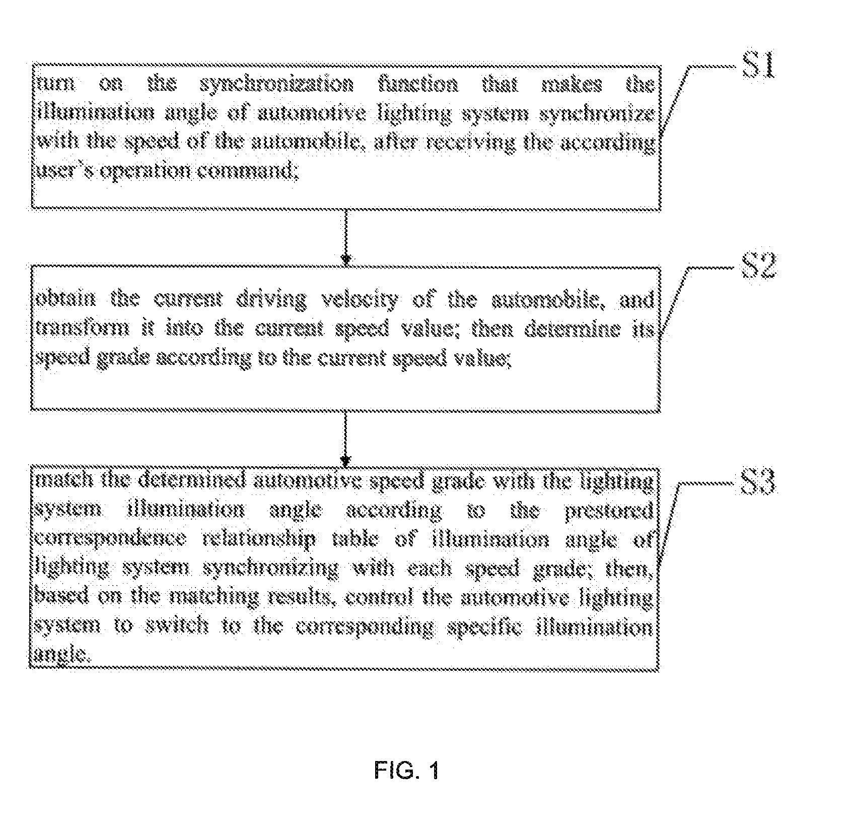
[0058]Refer to FIG. 1, which is the flow chart of a preferred embodiment of the controlling method of the present invention based on the lighting system illumination angle synchronizing with the automotive speed.

[0059]As shown in FIG. 1, the method comprises the following steps:

[0060]S1: turn on the function of lighting system illumination angle synchronizing with the automotive speed, after receiving the user's instructions.

[0061]First, the user switches on the device installed in the automobile which is able to accomplish the synchr...


PUM


Abstract

A controlling method and its application system based on the lighting system illumination angle of the automobile synchronizing with the automotive speed, comprises the following steps: turn on the synchronizing function after received the user's instructions; read and obtain the current automotive speed, look up the prestored correspondence relationship table, find out the specific synchronous angle according to current speed grade; then control the lighting system switching to the found specific illumination angle synchronizing with current speed grade, and achieve the synchronization of illumination angles and automotive speeds. Through applying the method and the application system stated in the present invention, the best illumination effects for an automobile can be achieved. Therefore, the present invention provides a safer lighting system with a better visual effect, which provides conveniences to users.

Description

CROSS-REFERENCES TO RELATED APPLICATIONS[0001]This application claims the priority of Chinese patent application no. 201310029436.9, filed on Jan. 25, 2013, the entire contents of all of which are incorporated herein by reference.FIELD OF THE INVENTION[0002]The present invention relates to the field of automotive electronics, and more particularly to a lighting system synchronize with the automotive speed, and a controlling method based on the lighting system illumination angle synchronizing with the automotive speed.BACKGROUND[0003]With the development of science and technology as well as the improvement of people's living standards, driving automobiles is becoming more and more popular, and more and more families own their automobiles.[0004]The existing automotive lighting system adjusts its illumination intensity according to the position of its filamentary cathode. When the cathode locates on its focus, high beam light will be emitted in parallel, and the light is more concentra...

Claims


Application Information

Patent Timeline
Patent Type & Authority Applications(United States)
IPC IPC(8): B60Q1/14
CPCB60Q1/085B60Q1/1423B60Q2300/112B60Q2300/054
Inventor ZHUANG, MINLU, PENG
Owner SHENZHEN PROTRULY ELECTRONICS CO LTD
Why Eureka
Try Eureka