
Drive unit for a revolving door with an integrated blocking device and/or braking device

a technology of braking device and revolving door, which is applied in the direction of magnetic circuit rotating parts, wing accessories, shape/form/construction, etc., can solve the problems that the advantages of installing multi-pole motors within a minimal space in the revolving door cannot be realized in an advantageous manner, and the turntile of the revolving door can be stopped extremely quickly, and the braking distance can be considerably reduced

Inactive Publication Date: 2014-07-17
DORMAKABA DEUT GMBH
View PDF3 Cites 6 Cited by
  • Summary
  • Abstract
  • Description
  • Claims
  • Application Information

AI Technical Summary

Benefits of technology

This patent describes a way to connect a multipole motor, which is a type of electric motor, to a turnstile in a revolving door without needing a gear unit. This is possible because the motor has an engagement device built in it that can intervene in the movement of the turnstile. This makes it possible to stop the turnstile quickly, especially when someone triggers a sensor and the turnstile could collide with them and get them hurt. The braking device in the motor helps achieve this quickly and safely.

Problems solved by technology

Electromotive braking actions may not be sufficient for this purpose, particularly when very high delay values of the turnstile must be reached for safety reasons.
If a wheel disk brake constructed in this way were coupled with a multipole motor, the advantages of the installation of the multipole motor within a minimal space in the revolving door could no longer be realized in an advantageous manner.

Method used


Image

  • Drive unit for a revolving door with an integrated blocking device and/or braking device
  • Drive unit for a revolving door with an integrated blocking device and/or braking device
  • Drive unit for a revolving door with an integrated blocking device and/or braking device

Examples


Embodiment Construction

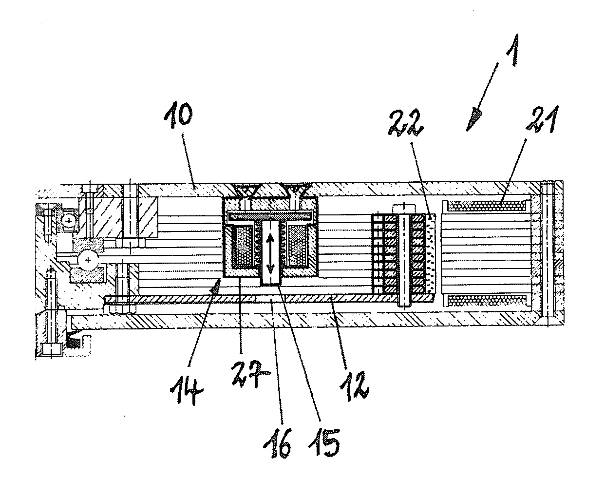
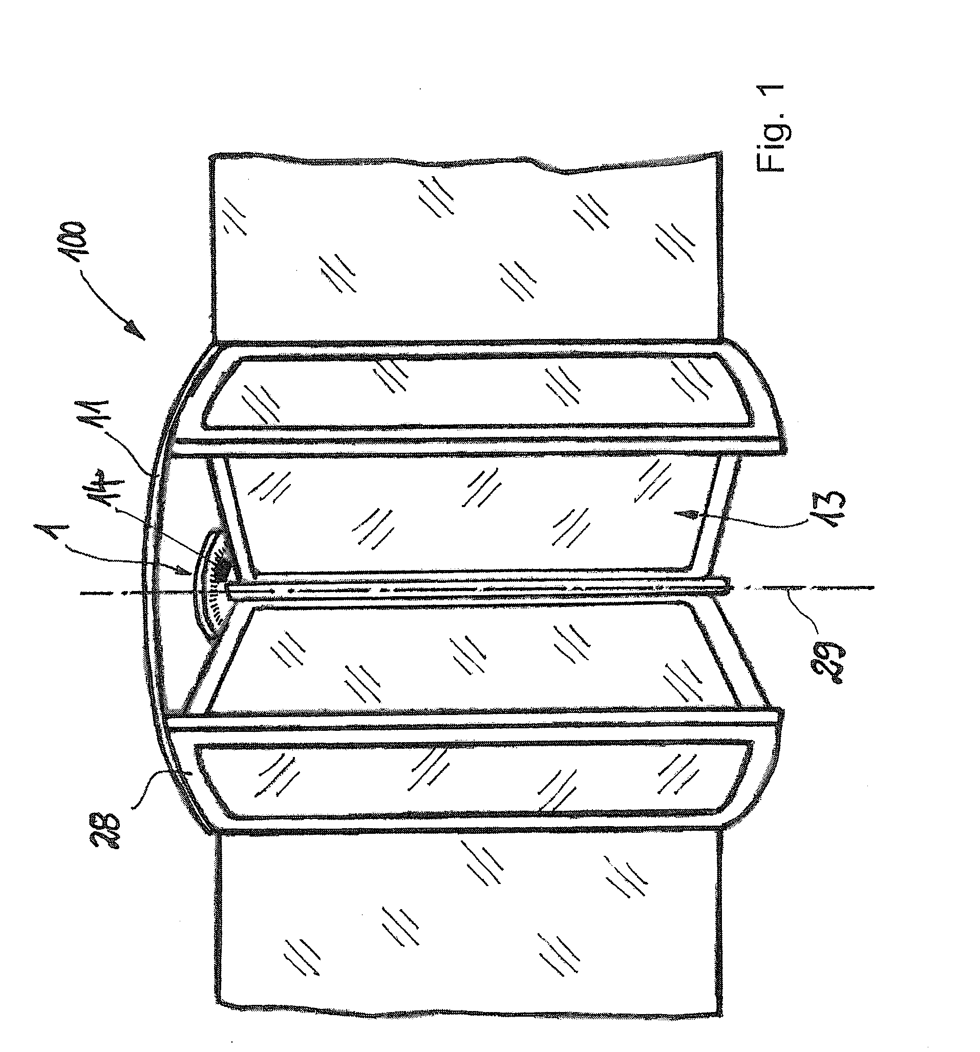
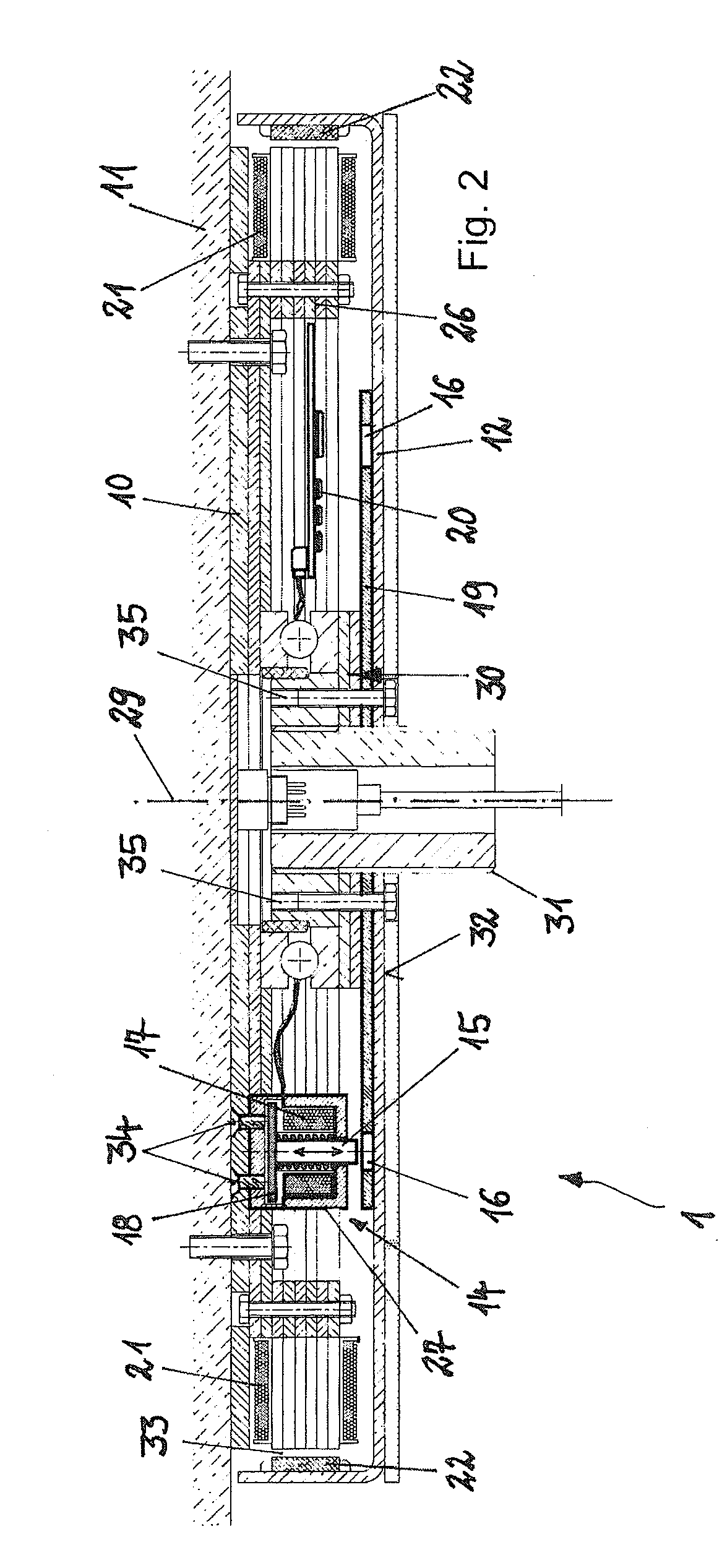
[0027]FIG. 1 is a schematic perspective view of a revolving door 100. The revolving door 100 has a frame 28, and a ceiling element of the frame 28 forms a structural component part 11 at which is arranged a multipole motor 1 that drives a turnstile 13 in rotation around a drive axis 29. Alternatively, the structural component part 11 can also form a floor-side component part of the revolving door 100 or of a building. The multipole motor 1 is accordingly located in a ceiling-mounted arrangement between the structural component part 11 and the turnstile 13. The multipole motor 1 has a flat-cylindrical, dish-like or disk-like basic form that makes it possible to arrange the multipole motor 1 on the ceiling.

[0028]In order to retard or block the rotational movement of the turnstile 13, an engagement device 14, only indicated schematically, is integrated in the multipole motor 1. The engagement device 14 makes it possible to retard the turnstile 13 in addition to an electromotive delayin...


PUM


Abstract

A drive unit for a revolving door having a turnstile includes: an electronically commutated multipole motor having: (i) a disk-shaped or cup-shaped stator part configured to be arrangable at a stationary structural component part of the revolving door, (ii) a disk-shaped or cup-shaped rotor part configured to be gearlessly connectable to the turnstile of the revolving door, and (iii) an engagement device arranged between the stator part and the rotor part, the engagement device being configured to intervene in rotational movement of the rotor part. The stator part and the rotor part are in a plane-parallel arrangement with respect to one another.

Description

BACKGROUND OF THE INVENTION[0001]1. Field of the Invention[0002]The present invention is directed to a drive unit for a revolving door with an electronically commutated multipole motor and a revolving door with a drive unit of this type.[0003]2. Description of the Related Art[0004]DE 10 2010 024 108 A1 shows a generic drive unit for a revolving door with an electronically commutated multipole motor. The multipole motor is dish-shaped and has a round, flat base structure. The multipole motor has an output shaft connected to a turnstile of the revolving door, and the revolving door can be driven by the multipole motor.[0005]Multipole motors are also known as torque motors and have coil elements that are arranged on a circular path and are in an oppositely facing relationship, for example, on the inner side, outer side or axially, to magnet elements, which are also arranged on a circular path so that a high-pole count, high-torque direct drive is formed. The rotor part of the multipole...

Claims


Application Information

Patent Timeline
Patent Type & Authority Applications(United States)
IPC IPC(8): H02P3/04E05F15/10H02K1/14H02K1/27H02K11/00
CPCH02P3/04E05F15/106H02K11/0068H02K1/2786H02K1/14E05Y2900/132E05F15/608H02K11/30H02K1/2791
Inventor BUSCH, SVEN
Owner DORMAKABA DEUT GMBH
Learn More