
Electrically assisted street scooter

a technology of electric assistance and street scooters, which is applied in the direction of skis, snowboards, sports equipment, etc., can solve the problems of difficulty or even danger in pushing the scooter with one leg, no electric assistance, and no adaptation of the leg push to the speed given by the motor

Active Publication Date: 2014-07-17
MICRO BEAM
View PDF38 Cites 76 Cited by
  • Summary
  • Abstract
  • Description
  • Claims
  • Application Information

AI Technical Summary

Benefits of technology

This patent describes an electric assisted scooter that is easier, safer, and has higher autonomy. The scooter has a drive circuit that automatically switches on when it is pushed and off when it is not used for a set amount of time, resulting in battery saving. Additionally, the scooter has a method to simulate low friction and lower street slope by controlling the speed after it reaches its peak speed.

Problems solved by technology

This document relates to an electric powered scooter, which is essentially or only powered by the motor; in fact it might be difficult or even dangerous to push the scooter with one leg when the motor is switched on, since one needs to adapt the leg push to the speed determined by the motor.
Again, adaptation of the leg push to the speed given by the motor is difficult.
A drawback is that no electric assistance is provided when the scooter is pushed until the threshold speed has been reached.
A further drawback is that once the motor has been started the speed of the scooter is almost independent of the efforts made by the user.
If the threshold speed is too low, the motor can be inopportunely started, for example when a user walks and pushes his scooter beside him.

Method used


Image

  • Electrically assisted street scooter
  • Electrically assisted street scooter
  • Electrically assisted street scooter

Examples


Embodiment Construction

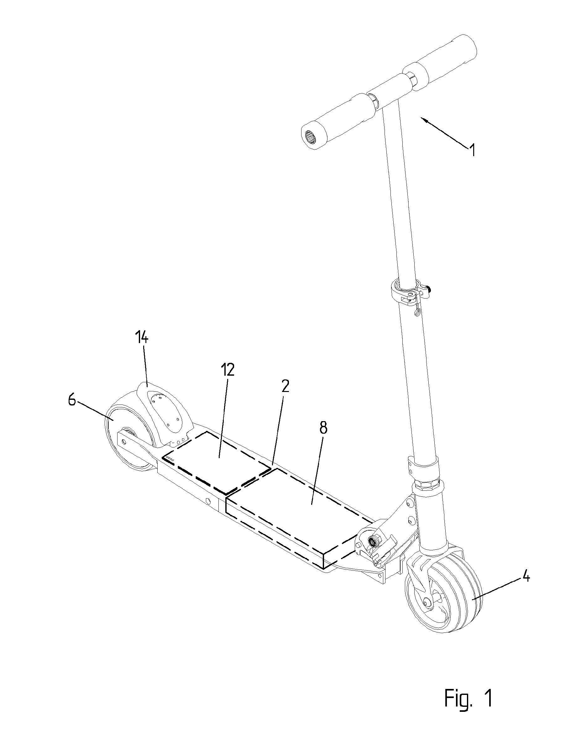
[0087]The street scooter of FIG. 1 comprises a deck (or platform 2), a handle bar 1, a front wheel 4 and a rear wheel 6. The deck is preferably made of aluminium. The street scooter is preferably a foldable microscooter, for example a foldable microscooter, although the different aspects of the invention could also be applied to other types of street scooters, including non foldable scooters or skateboards.

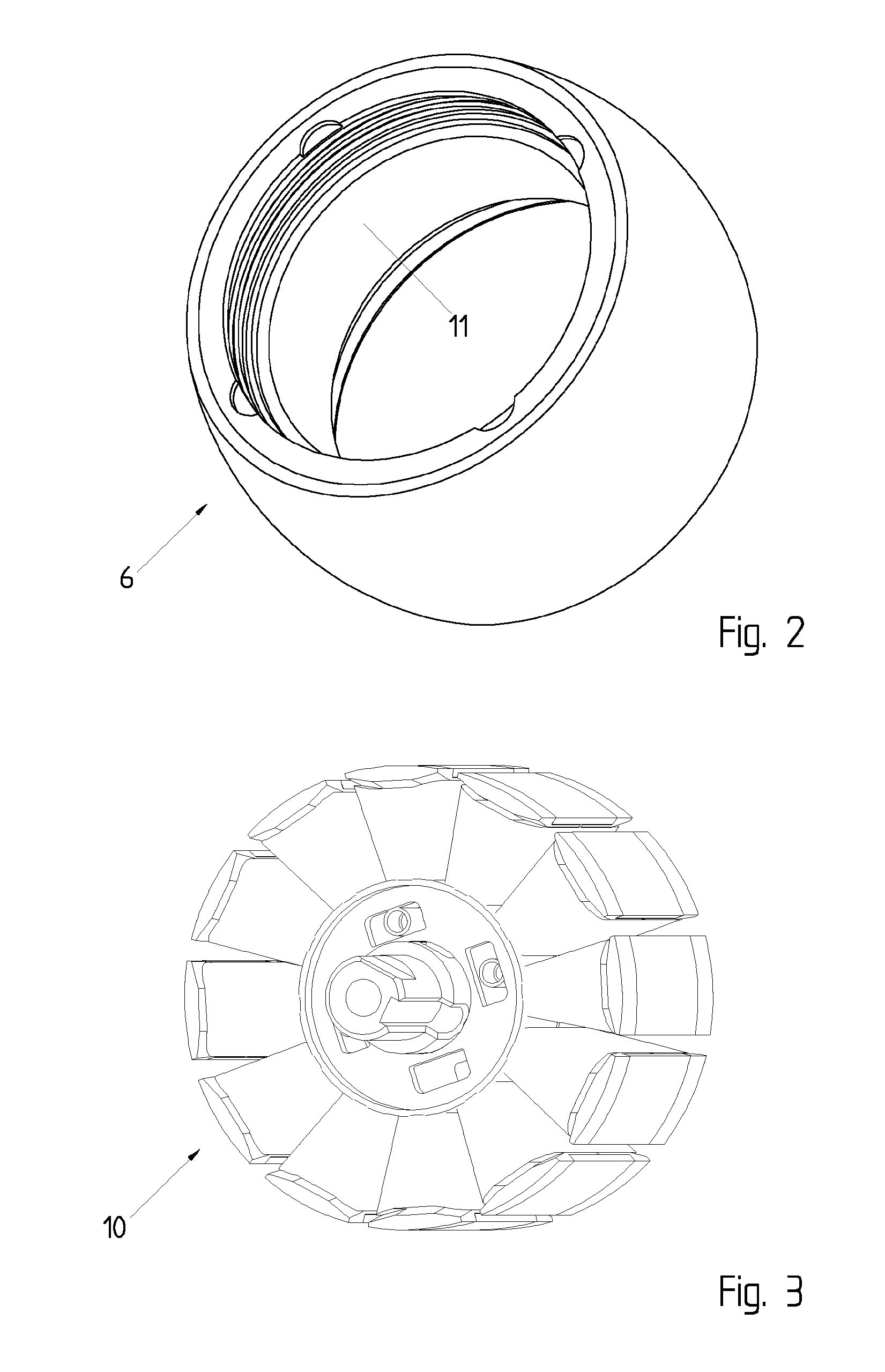
[0088]An electrical motor fits in one of the wheels, for example in the rear wheel (FIGS. 2 and 3) of the street scooter. The motor could be a brushless DC motor, or another DC motor. It comprises a central stator 10 with coils and permanent magnets within the external rotor 11. In this example, the motor has been mounted within the rear wheel but could have been mounted within the front wheel 4; furthermore, it is also possible to mount a motor within both two wheels. In one embodiment, the front wheel and / or the rear wheel can be doubled (front built with 2 wheels and / or rear bu...


PUM


Abstract

An electrically assisted street scooter includes a handlebar, a deck, front and back wheels, a battery pack integral with the deck, an electrical motor for driving at least one of the wheels, and a drive circuit for controlling electrical supply to the electrical motor from the battery pack. The drive circuit includes a switch for setting the drive circuit in a low power-mode where the electrical motor is not powered when the switch is off, or for setting the drive circuit in a drive mode where the electrical motor can be powered when the switch is on. An auto-power on circuit automatically switches the switch on when a user pushes the street scooter. An auto-power off circuit automatically switches the switch off when the scooter is not used during a predetermined duration. The level of electrical assistance is determined based on the peak value after each leg push.

Description

[0001]The present invention relates to a leg propelled street scooter with electrical assistance. The present invention applies in particular to foldable microscooter with electrical assistance, and to a scooter that could be used for instance by commuters using public transportation to allow them reaching public transport from home / office with no time loss.RELATED ART[0002]Electric powered scooters are known. More particularly, an electric scooter is disclosed in U.S. Pat. No. 5,775,452. This document suggests batteries held to the underside of the platform or deck of the scooter. A motor directly drive the rear wheel when a switch on the steering handle is actuated. This document relates to an electric powered scooter, which is essentially or only powered by the motor; in fact it might be difficult or even dangerous to push the scooter with one leg when the motor is switched on, since one needs to adapt the leg push to the speed determined by the motor.[0003]U.S. Pat. No. 6,318,49...

Claims


Application Information

Patent Timeline
Patent Type & Authority Applications(United States)
IPC IPC(8): B62M6/00
CPCB62M6/00B62K3/002B62M6/65B62H5/00B62H5/08
Inventor BIELER, THIERRYCARDOLETTI, LAURENTFLEURY, CHRISTIANKOECHLI, CHRISTIANTINGUELY, SIMON
Owner MICRO BEAM
Learn More