
Piezoelectric component and method for producing a piezoelectric component

a piezoelectric component and piezoelectric technology, applied in piezoelectric/electrostrictive transducers, generators/motors, transducer types, etc., can solve the problems of reducing the effective cross sectional area for signal generation with respect to the required installation space, affecting the sensor signal, and requiring additional contact space for connection, etc., to achieve optimal signal generation, facilitate optimal signal reduction, and high conductivity

Inactive Publication Date: 2014-07-10
ROBERT BOSCH GMBH
View PDF7 Cites 1 Cited by
  • Summary
  • Abstract
  • Description
  • Claims
  • Application Information

AI Technical Summary

Benefits of technology

The invention provides a piezoelectric component and method with improved design and functionality. The component has a first piezoceramic layer, at least one second piezoceramic layer, and an electrically conductive contact layer which is located between the first and second layers. The contact layer is inserted via a joining material between the first and second layers. This design reduces signal deviations over the service life of the component, and care must be taken to prevent changes in the joining material during operation. The electrically conductive contact layer can be formed by a thin metal layer with high conductivity and a homogeneous microstructure, and the recesses on the ceramic layers or layers of different size are not required. The joining material compensates for tolerances, waviness, or surface irregularities of the contact layer or ceramic layers during production. The amount of joining material can be adjusted, and the distance between the piezoceramic layers can be reduced for signal generation and material consumption purposes.

Problems solved by technology

These embodiments have the disadvantage that the effective cross sectional area for signal generation is reduced with respect to the required installation space.
This negatively impacts the sensor signal.
In addition, an additional space for contacting is required for the connection.
Furthermore, the problem arises in particular in applications like when measuring the pressure in fuel injectors that a high pressure resistance has to be ensured.

Method used


Image

  • Piezoelectric component and method for producing a piezoelectric component
  • Piezoelectric component and method for producing a piezoelectric component
  • Piezoelectric component and method for producing a piezoelectric component

Examples


Embodiment Construction

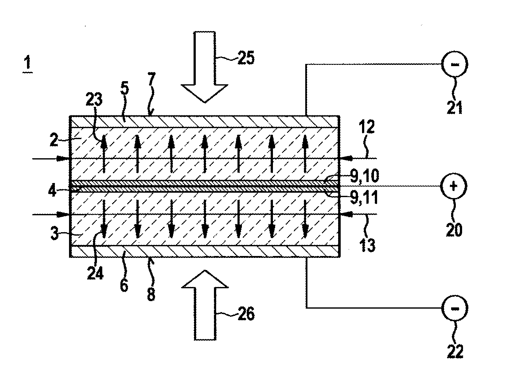
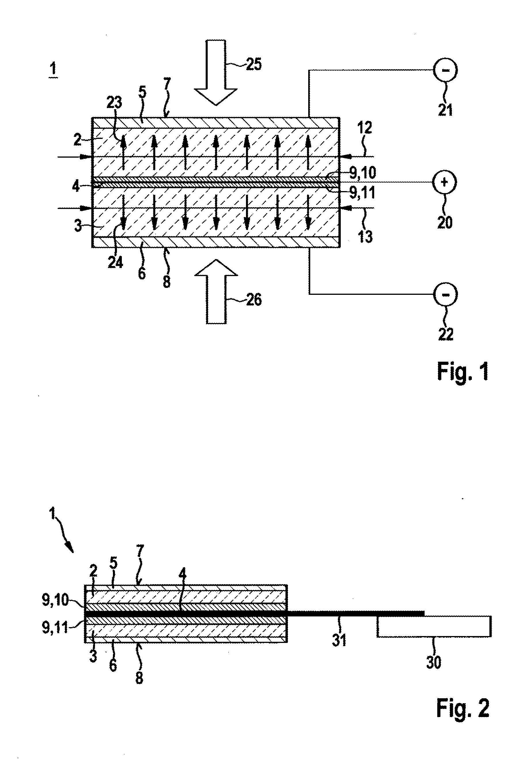
[0017]FIG. 1 shows a piezoelectric component 1 corresponding to a first exemplary embodiment and shown in a schematic sectional representation. The piezoelectric component 1 preferably serves as a piezoelectric sensor 1. The piezoelectric sensor 1 can particularly be used in fuel injection systems. The piezoelectric sensor 1 can, for example, serve as a needle closing sensor which monitors a closing of a valve needle of a fuel injection valve. At the same time, the sensor 1 can also measure a pressure profile within a fuel chamber of the fuel injection valve. The sensor 1 can also be designed as a combustion chamber pressure sensor 1 which directly or indirectly measures the pressure in a combustion chamber of an internal combustion engine. The piezoelectric sensor 1 is however also suited to other applications, in particular in the automotive field. The sensor 1 can also be specifically used as an operating means sensor for hydraulic or pneumatic applications

[0018]The piezoelectric...


PUM

PropertyMeasurementUnit
Timeaaaaaaaaaa
Electrical conductivityaaaaaaaaaa
Piezoelectricityaaaaaaaaaa

Abstract

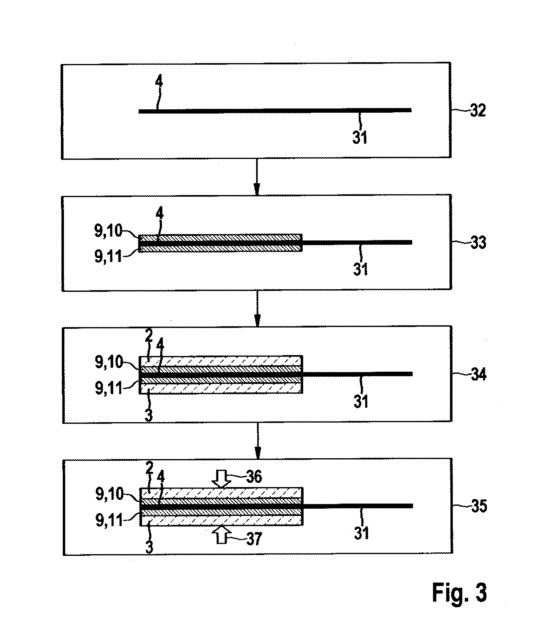
An electrically conductive contact layer (4) is provided with a joining material (9) during a method for producing a piezoelectric component (1), in particular a piezoelectric sensor (1). To this end, the electrically conductive contact layer (4) can be dipped into a paste that serves to form the joining material (9). The contact layer (4) provided with the joining material (9) is subsequently disposed between a first piezoceramic layer (2) and a second piezoceramic layer (3). The contact layer (4) is then inserted via the joining material (9) between the first piezoceramic layer (2) and the second piezoceramic layer (3), wherein a pressure is applied to the first piezocermaic layer (2) against the second piezoceramic layer (3).

Description

BACKGROUND OF THE INVENTION[0001]The invention relates to a piezoelectric component, in particular a piezoelectric sensor, as well as to a method for producing such a piezoelectric component. The invention relates specifically to the area of piezoceramic pressure sensors which are used for measuring pressure in motor vehicles.[0002]The German patent publication DE 10 2010 000 827 A1 discloses a fuel injector having a force or pressure sensor. In the case of said disclosed fuel injector, the force or pressure sensor is associated with a control chamber, the pressure of which determines the strokes or positions of a nozzle needle. The profile of the control chamber pressure can be acquired using the force or pressure sensor.[0003]When designing a piezoelectric pressure sensor, it is conceivable that ceramic layers and electrode layers disposed between said ceramic layers are provided, wherein, in order to contact an electrode layer, the associated ceramic layer has a recess at this lo...

Claims


Application Information

Patent Timeline
IPC IPC(8): H01L41/047H01L41/293
CPCH01L41/0472H01L41/0477H01L41/293H01L41/0475H01L41/1132H01L41/313Y10T29/42H10N30/875H10N30/302H10N30/073H10N30/877H10N30/063H10N30/872
Inventor MELCHER, REINHOLDGUENTHER, MICHAEL
Owner ROBERT BOSCH GMBH
Learn More