
Organic el display device

Active Publication Date: 2014-07-10
JAPAN DISPLAY INC
View PDF5 Cites 6 Cited by
  • Summary
  • Abstract
  • Description
  • Claims
  • Application Information

AI Technical Summary

Benefits of technology

The present invention aims to provide an organic EL display device that reduces external light reflection to improve contrast while maintaining brightness. This is achieved by using a circularly polarizing plate that absorbs half of the external light and light emission from the display device. However, this leads to a problem of reducing the brightness of organic EL display devices that display a bright image with lower power consumption. Increasing the supply power to increase brightness also causes deterioration of the light emitting layer. The invention proposes a solution to this problem by increasing the efficiency of the circularly polarizing plate to absorb external light and minimize the adverse effects on the display device.

Problems solved by technology

That is, the white brightness Bw is (½)·Bw0 which is half of that when the circularly polarizing plate is not arranged, resulting in such a problem that the brightness reduction becomes large.
However, one of features of the organic EL display device is that the organic EL display device can display a bright image with lower power consumption than a liquid crystal display device requiring a backlight, and increasing a supply power to increase the brightness diminishes the above feature.
Also, there arises such a problem that the deterioration of a light emitting layer is accelerated with an increase in the supply power.
That is, although the white brightness Bw can be increased more than that when the circularly polarizing plate is provided, there arises such a problem that the reflection brightness Br is also increased to decrease contrast.

Method used


Image

  • Organic el display device
  • Organic el display device
  • Organic el display device

Examples


Embodiment Construction

[0024]An organic EL display device according to an embodiment of the present invention will be described with reference to the accompanying drawings.

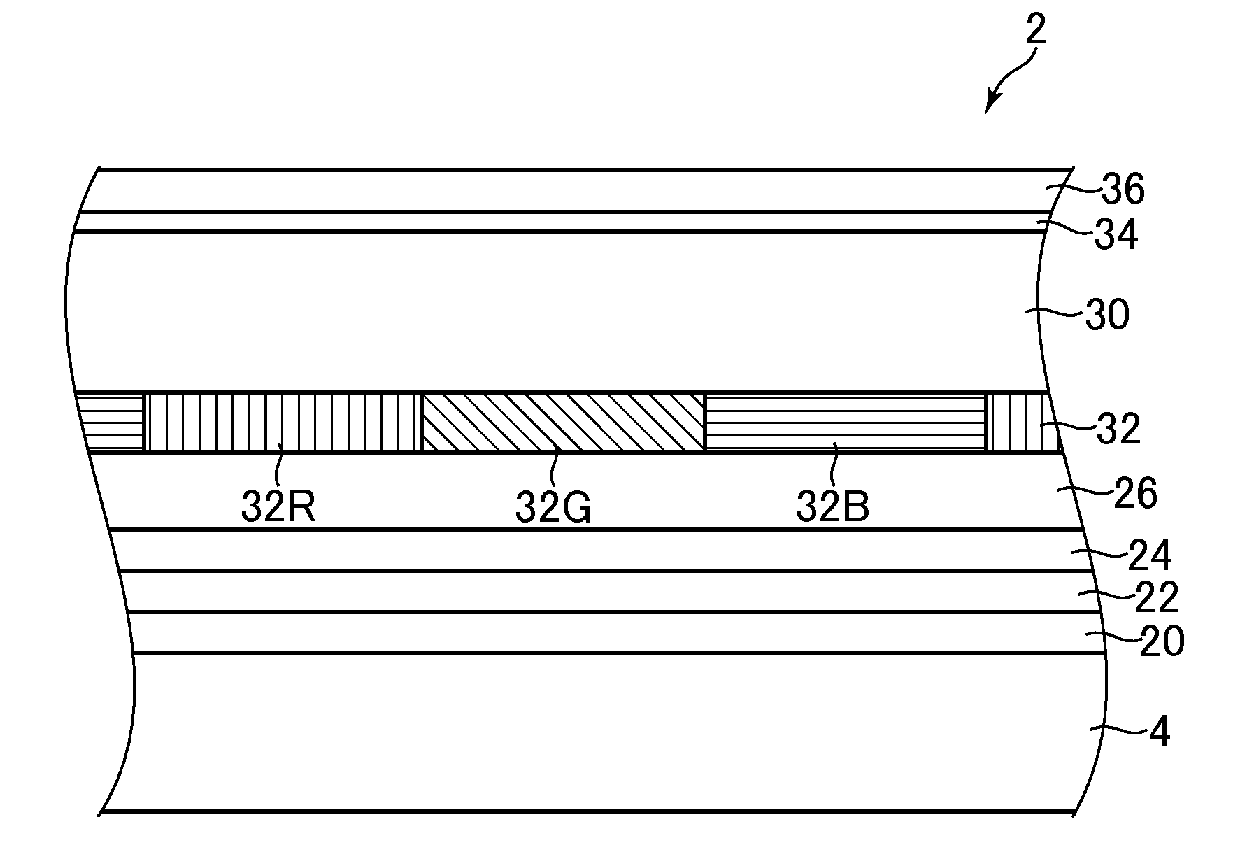
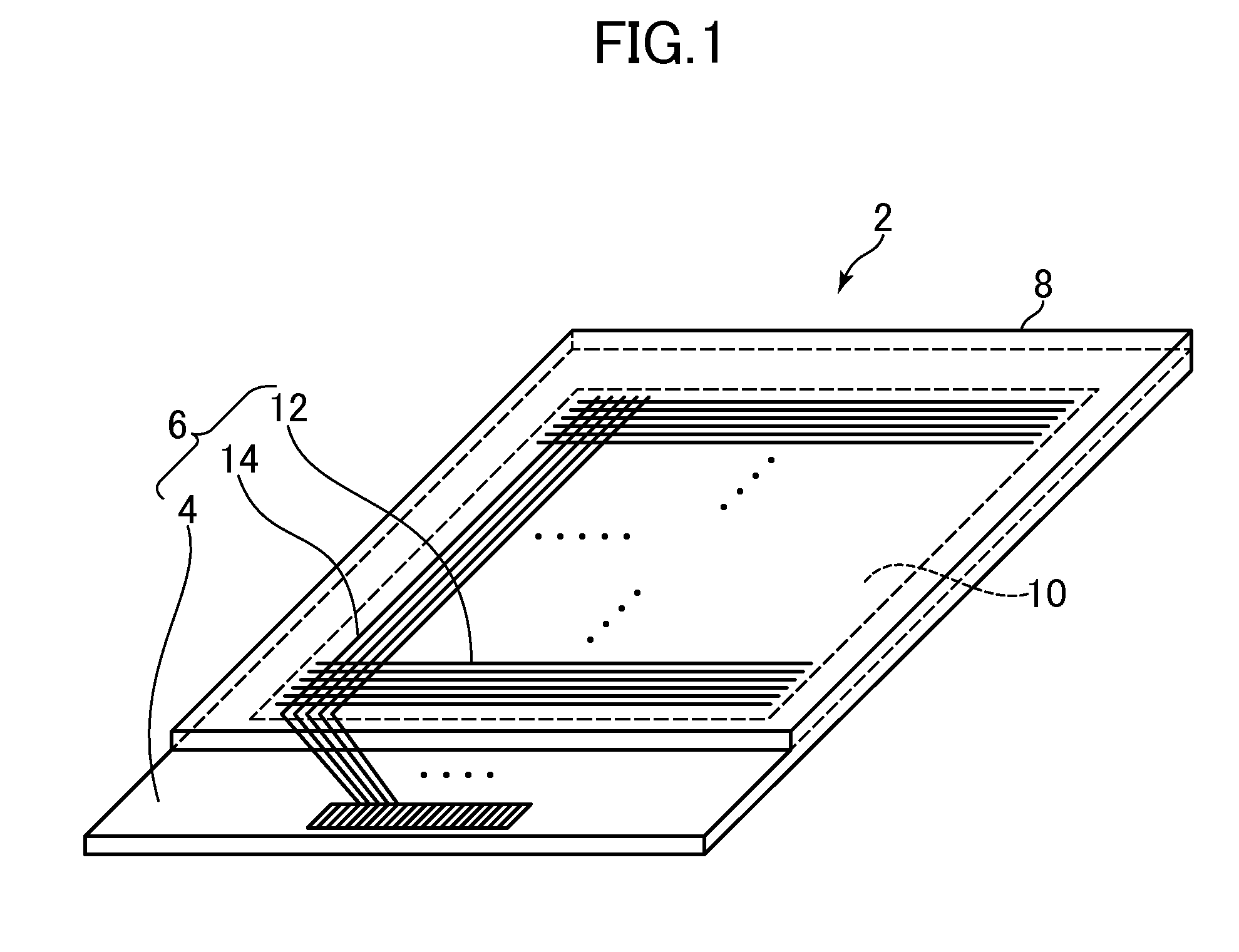
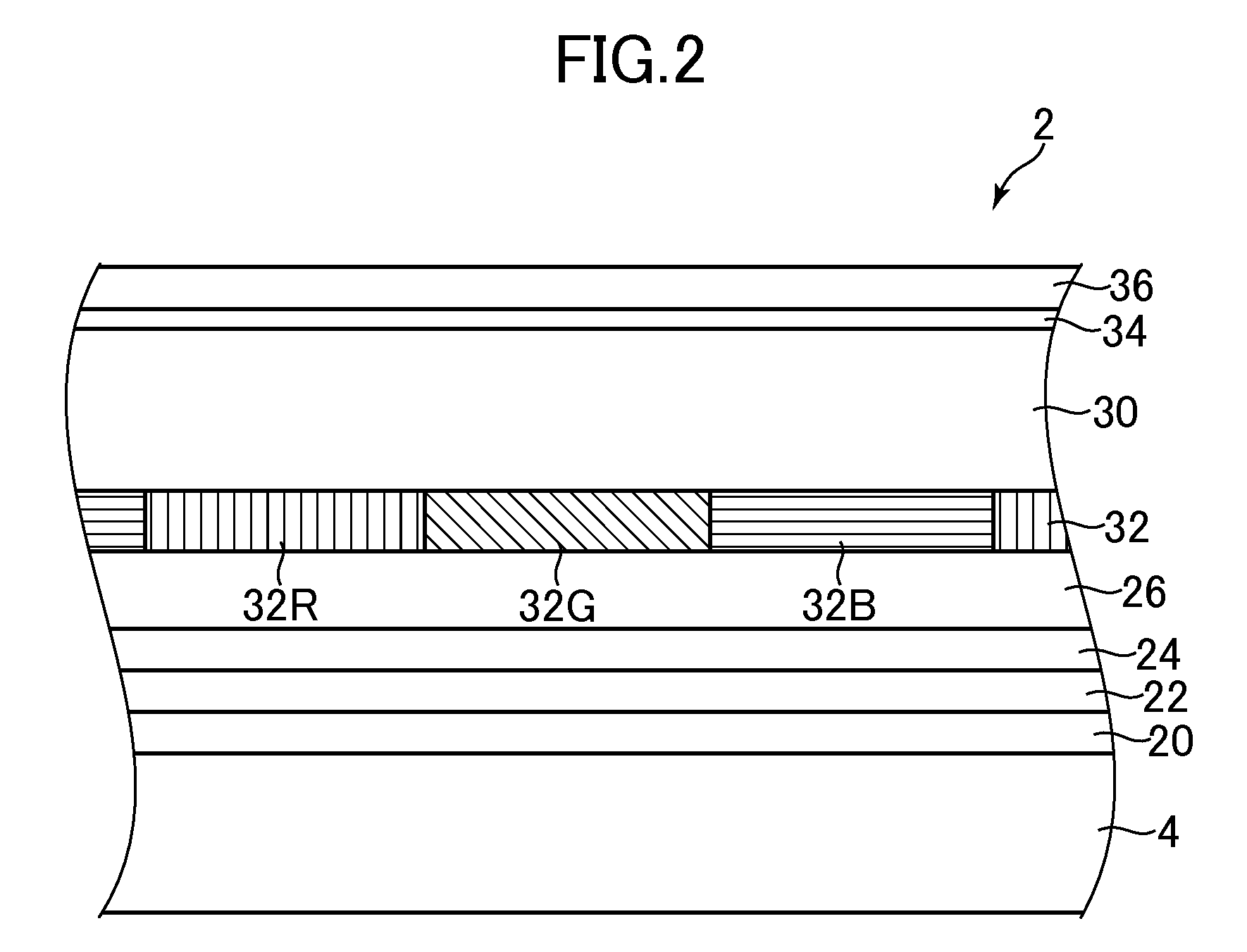
[0025]FIG. 1 is a schematic perspective view illustrating an organic EL display device 2 according to an embodiment of the present invention. The organic EL display device 2 according to this embodiment includes a TFT substrate 6 in which a plurality of thin film transistors is arranged on a glass substrate 4 in a matrix, and a sealing substrate 8 bonded on the TFT substrate 6. Also, a plurality of pixels to be subjected to a display control is arranged in a display area 10 of the organic EL display device 2, and the organic EL display device 2 displays a color image in the display area 10 on the sealing substrate 8 side. In the organic EL display device 2, red (R) pixels, green (G) pixels, and blue (B) pixels are arranged in a striped manner in the display area 10. That is, pixels having the same color are aligned in a vertical directi...


PUM


Abstract

An organic EL display device ensures brightness and improves a contrast ratio by a reduction in external light reflection. The organic EL display device includes a wavelength selective absorption filter that absorbs a light in a given absorption spectrum uniform in a display region. An absorption spectrum has a negative correlation with an outgoing spectrum in which respective spectrums of R pixels, G pixels, and B pixels are synthesized together.

Description

CROSS-REFERENCE TO RELATED APPLICATION[0001]The present application claims priority from Japanese application JP2013-000032 filed on Jan. 4, 2013, the content of which is hereby incorporated by reference into this application.BACKGROUND OF THE INVENTION[0002]1. Field of the Invention[0003]The present invention relates to an organic EL display device, and more particularly to a technique for reducing an external light reflection to improve a contrast ratio.[0004]2. Description of the Related Arts[0005]An external light reflection on a display surface of a display device such as an organic EL display device reduces a contrast ratio of an image. As one of measures against this problem, there is a structure in which a circularly polarizing plate is arranged on a display surface. As another of the measures, there is a structure in which a neutral density (ND) filter that evenly absorbs a visible light wavelength range is arranged on the display surface.SUMMARY OF THE INVENTION[0006]A rat...

Claims


Application Information

Patent Timeline
IPC IPC(8): H01L51/52H01L27/32
CPCH01L27/322H01L51/5284H10K59/38H10K59/8792H10K50/865
Inventor TOJO, TOSHIO
Owner JAPAN DISPLAY INC
Learn More